
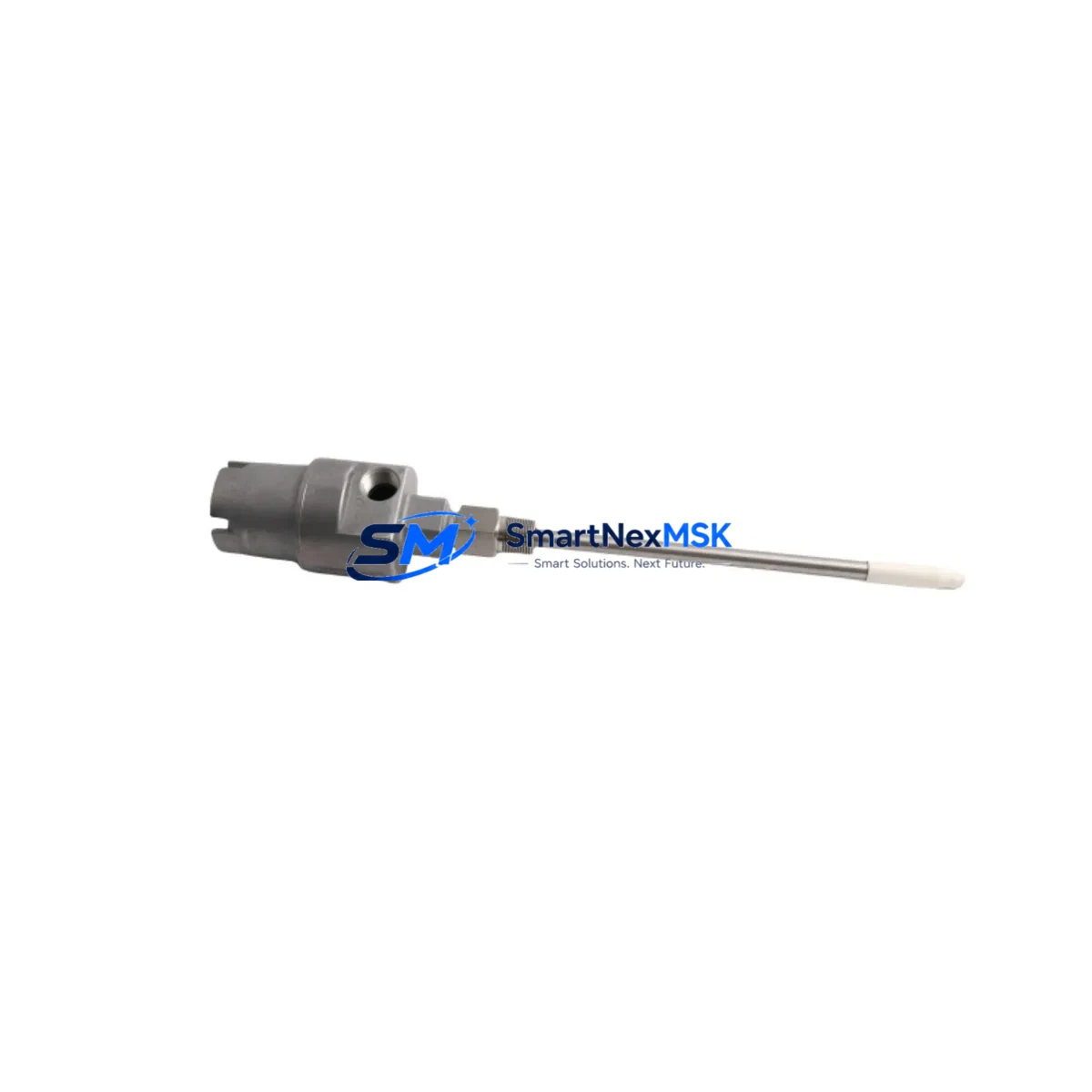
Bently Nevada 21000-16-05-25-020-04-02 Retrofit-Ready Proximity Probe Housing for 21000 Series Control Systems
The Bently Nevada 21000-16-05-25-020-04-02 is a precision-engineered proximity probe housing assembly designed for seamless integration into legacy and modernized vibration monitoring systems. As industrial facilities transition aging machinery protection infrastructure toward current-generation platforms, this component serves as a critical link between discontinued field hardware and active monitoring architectures — enabling smooth, low-risk retrofits without requiring full sensor chain replacement.
Engineered to the dimensional and electrical specifications of the Bently Nevada 21000 Series, this housing assembly is compatible with the 3300 XL and 3500 Series monitoring systems, making it a preferred choice for maintenance engineers managing turbomachinery, compressors, pumps, and rotating equipment in power generation, oil & gas, petrochemical, and heavy industrial environments. Whether you are replacing a failed unit, restocking critical spares, or executing a planned control system upgrade, the 21000-16-05-25-020-04-02 delivers verified dimensional compliance and electrical performance.
Upgrade Compatibility Table
| Parameter | Details |
|---|---|
| SKU / Part Number | 21000-16-05-25-020-04-02 |
| Brand / OEM | Bently Nevada |
| Series | 21000 Series |
| Compatible Monitors | Bently Nevada 3300 XL, 3500 Series |
| Probe Type | Proximity (Eddy Current) |
| Housing Thread / Dimensions | Per 21000 Series mechanical specification |
| Cable / Extension Compatibility | 330130 / 330180 Series extension cables |
| Driver / Proximitor Compatibility | 3300 XL 8mm, 3500/42M Proximitor modules |
| Installation Requirement | Standard probe bracket; verify gap voltage at commissioning |
| Communication Protocol | Analog 4–20 mA / voltage output to monitor rack |
| Replacement Recommendation | Direct drop-in for 21000 Series housings; verify extension cable length |
| Commissioning Focus | Gap voltage setting, polarity check, signal cable shielding |
| Warranty | 12 Months from date of shipment |
| Origin | China (CN) |
Retrofit Planning for Existing Automation Systems
When planning a retrofit around the 21000-16-05-25-020-04-02, engineers must evaluate the complete sensor chain from the probe tip through to the monitor rack. The housing assembly interfaces directly with the 330130-080-00-00 or 330180-X0-05 extension cables — verifying cable length and connector compatibility is the first step before ordering replacement hardware. The extension cable connects to a 3300 XL Proximitor or a 3500/42M Proximitor/Monitor module seated in the 3500 rack, and any mismatch in cable impedance or connector type will affect gap voltage calibration.
Within the 3500 rack, the Proximitor module communicates with the 3500/01 Rack Interface Module (RIM) and the 3500/20 Rack Power Module, both of which must be confirmed operational before introducing new sensor hardware. If the existing rack is running on a legacy 3300 Series monitor, the retrofit may require a parallel upgrade to a 3500/40M Proximitor/Monitor or 3500/42M to maintain system certification and alarm relay functionality.
For facilities operating older DCS or safety systems that receive vibration signals from the 3500 rack via Modbus RTU or 4–20 mA hardwired loops, the signal output configuration of the new Proximitor module must be verified against the existing DCS input card wiring. In many brownfield sites, the 3500/92 Communication Gateway Module handles protocol translation between the monitor rack and the plant DCS — confirm that gateway firmware is current before commissioning the new probe assembly.
HMI screens tied to vibration trend displays should be reviewed after sensor replacement. If the facility uses a System 1 Evolution software platform for machinery health monitoring, the new probe channel must be re-mapped and the baseline vibration signature re-established after installation. Technicians should also verify that the 3500/22M Transient Data Interface is capturing the correct channel data if transient analysis is part of the monitoring scope.
For sites where the probe housing is mounted in a hazardous area, confirm that the replacement assembly carries the appropriate intrinsic safety or explosion-proof certification consistent with the original installation documentation. Coordinate with the site safety officer before breaking into the sensor circuit in classified zones.
Downtime Control During System Migration
Minimizing unplanned downtime during a proximity probe housing replacement requires a structured pre-outage preparation protocol. Before the maintenance window opens, technicians should pre-configure the replacement 21000-16-05-25-020-04-02 on the bench — verifying thread engagement, connector seating, and cable continuity — so that field installation time is limited to mechanical mounting and gap setting only.
The original gap voltage reading should be recorded from the 3500 monitor display or System 1 trend historian before the probe is removed. This reference value allows the technician to set the replacement probe to the same nominal gap (typically –10.0 to –11.0 VDC for 8 mm probes) without requiring a full vibration baseline re-run during the outage window. If the machine cannot be taken offline, a hot-swap procedure using a spare Proximitor channel — where available in the 3500 rack — can allow the new probe to be commissioned on a secondary channel while the primary channel remains active.
Program logic in the associated PLC or safety system that processes the vibration OK relay output from the 3500 rack should not require modification for a like-for-like probe housing replacement. However, if the retrofit involves a monitor module upgrade (e.g., from 3300 to 3500 Series), the relay output wiring and logic mapping must be reviewed and tested under simulated conditions before returning the machine to service. Maintaining a written commissioning checklist — covering gap voltage, signal cable shielding, alarm setpoint verification, and relay output test — ensures that no step is missed under time pressure.
Retrofit Support FAQ
Q1: Is the 21000-16-05-25-020-04-02 a direct replacement for the original Bently Nevada part?
A: Yes. This housing assembly is manufactured to the dimensional and electrical specifications of the original 21000 Series part. It is intended as a drop-in replacement for failed or end-of-life units in existing 21000 Series probe installations. Verify extension cable compatibility and gap voltage after installation.
Q2: What commissioning steps are required after installing this probe housing?
A: After mechanical installation, set the probe gap to achieve the target gap voltage specified for your Proximitor model (typically –10.0 to –11.0 VDC for standard 8 mm configurations). Verify signal cable shielding continuity, confirm the OK relay output is active at the 3500 monitor, and check that vibration trend data is updating correctly in your monitoring software before returning the machine to service.
Q3: Can this housing be used with both 3300 and 3500 Series monitors?
A: The 21000 Series probe housing is mechanically and electrically compatible with both the 3300 XL and 3500 Series Proximitor modules. Confirm that the extension cable length and impedance match the Proximitor model in use, as different Proximitor versions have specific cable length requirements that affect calibration range.
Q4: What warranty coverage is provided, and has the unit been tested before shipment?
A: All units carry a 12-month warranty from the date of shipment. Each assembly undergoes pre-shipment functional verification including dimensional inspection and electrical continuity checks. Units are packaged to OEM standards to prevent transit damage. Contact our team for warranty claims or technical support after installation.
© 2026 SMARTNEXMSK. All rights reserved.
Original Source: https://smartnexmsk.com
Contact: [email protected] | +86 18259474341



