
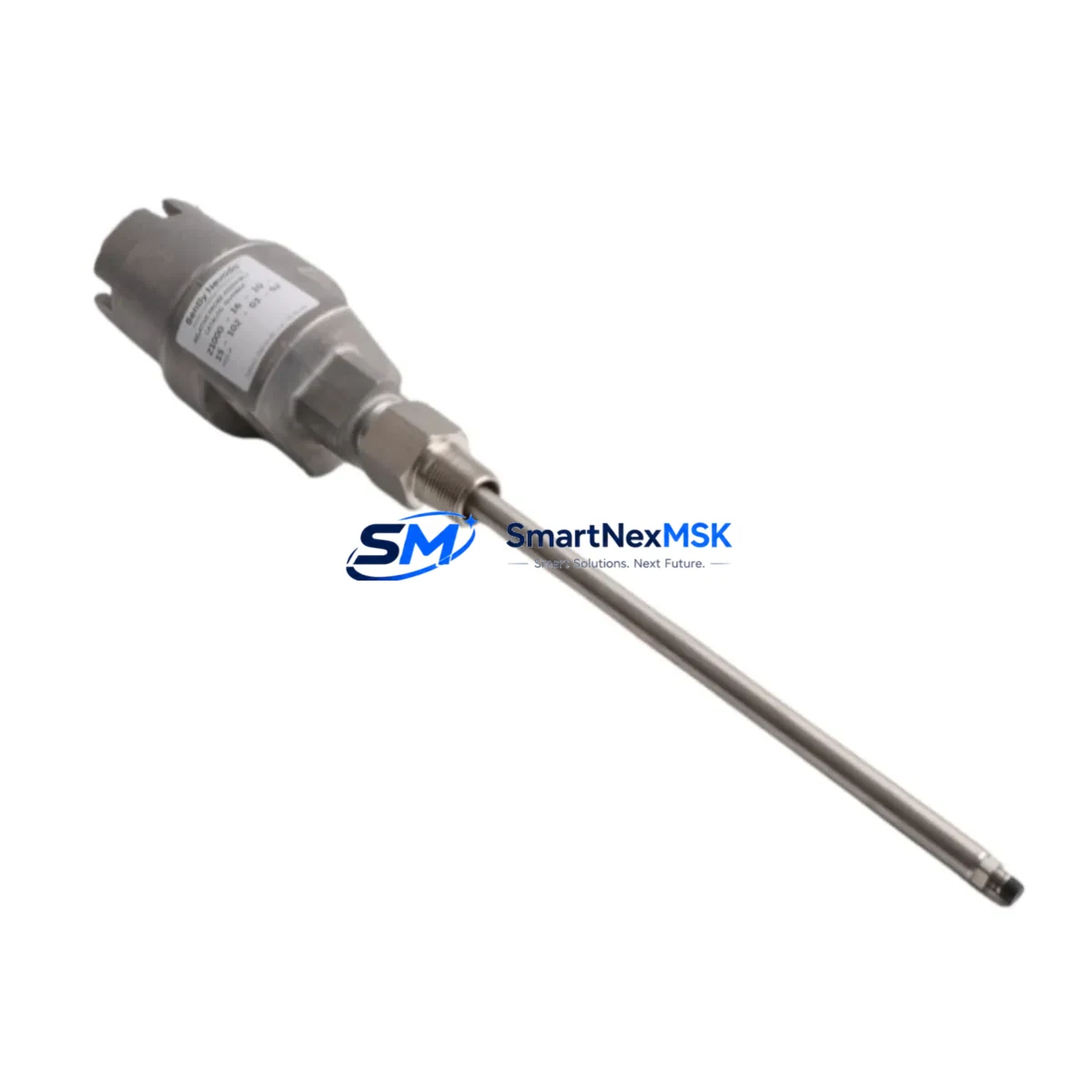
Bently Nevada 21000-16-10-00-103-04-02 3300 XL Probe: Compatible Retrofit & Smooth System Upgrade
The Bently Nevada 21000-16-10-00-103-04-02 is a 16mm proximity probe engineered for the Bently Nevada 3300 XL continuous vibration monitoring platform. Widely deployed in turbomachinery protection systems across power generation, oil & gas, and petrochemical industries, this probe is the preferred drop-in replacement for aging or discontinued proximity transducer assemblies operating within the 3300 XL signal conditioning chain.
When an existing 3300 XL proximity probe reaches end-of-life or becomes unavailable through OEM channels, the 21000-16-10-00-103-04-02 provides a verified retrofit path that preserves the original measurement chain without requiring reprogramming of the Bently Nevada 3300/16 XL monitor cards or reconfiguration of the System 1 software database. The probe maintains the standard -24 VDC bias voltage, 200 mV/mil (7.87 V/mm) sensitivity, and 5-90 mil (0.127-2.286 mm) linear range that the 3300 XL signal conditioner expects, ensuring seamless compatibility with installed 3300 XL 8mm and 3300 XL 16mm extension cable assemblies.
For facilities managing a fleet of rotating machinery, this probe is commonly paired with the Bently Nevada 330130 or 330180 series extension cables and the 330500 series proximitor sensors. Retrofit projects that involve replacing multiple transducer assemblies simultaneously should also account for the 3300/16 XL monitor card slot assignments and verify that the 3500/42M or 3500/40M proximity monitor modules are configured to accept the probe output range before commissioning.
Upgrade Compatibility Table
| Parameter | 21000-16-10-00-103-04-02 | Notes / Retrofit Guidance |
|---|---|---|
| Probe Diameter | 16 mm | Matches standard 3300 XL 16mm probe bore; no mechanical modification required |
| Sensitivity | 200 mV/mil (7.87 V/mm) | Compatible with 3300 XL and 3500 series signal conditioners |
| Bias Voltage | -24 VDC nominal | Verify power supply rail on existing 3300/16 XL or 3500/42M card |
| Linear Range | 5-90 mil (0.127-2.286 mm) | Set gap at 50 mil (1.27 mm) nominal during installation |
| Cable / Extension | Compatible with 330130 / 330180 series | Confirm extension cable length matches original assembly |
| Communication | Analog output via proximitor | No protocol migration required; integrates with existing Modbus or FOUNDATION Fieldbus gateways |
| Replacement Path | Direct replacement for discontinued 21000-series probes | No firmware or System 1 database changes required |
| Installation | Threaded mount, standard 3300 XL bracket | Verify bracket thread pitch before installation |
| Warranty | 12 Months | Covers manufacturing defects; includes pre-shipment functional test report |
Retrofit Planning for Existing Automation Systems
A successful retrofit of the 21000-16-10-00-103-04-02 begins well before the probe arrives on site. Engineering teams should pull the existing loop drawing to confirm the proximitor model – typically a Bently Nevada 330500-02-05 or 330500-02-CN – and verify that the driver supply voltage and output scaling have not been field-modified. If the machine train uses a 3500 rack with a 3500/42M four-channel proximity monitor, the channel configuration stored in the rack non-volatile memory must be reviewed in Rack Configuration software to confirm the probe type, gap voltage, and alert/danger setpoints remain valid for the replacement unit.
Power budget verification is equally critical. The 3300 XL proximitor draws current from the monitor card internal -24 VDC supply. When multiple probes share a single 3300/16 XL card, the aggregate current draw must remain within the card rated output capacity. Adding a replacement probe to a partially populated card is straightforward, but full-card replacements in a dense rack – particularly those also hosting 3300/55 temperature monitor cards or 3300/65 tachometer cards – require a power audit before energizing.
Terminal wiring follows the standard three-wire proximitor scheme: shield, signal, and common. When replacing a probe in a live control cabinet, technicians should use the 3500 rack inhibit function or the System 1 software bypass to suppress spurious alarms during the gap-setting procedure. After the probe is installed and the gap is set to the nominal 50 mil (1.27 mm) using a non-conductive feeler gauge, the DC gap voltage should read between -10.0 VDC and -10.4 VDC at the proximitor output terminal. This reading should be logged and compared against the original commissioning record before the bypass is removed.
For machine trains that also require shaft reference marks, the Bently Nevada 330180-91-05 Keyphasor probe – installed on the same shaft – must be re-gapped and its once-per-revolution pulse verified in System 1 before returning the unit to service. HMI screens built on GE iFIX, Wonderware InTouch, or Emerson DeltaV Live that display vibration trend data from the 3300 XL or 3500 rack do not require modification, as the tag names and OPC server addresses remain unchanged when a like-for-like probe replacement is performed.
Downtime Control During System Migration
Minimizing unplanned downtime during a proximity probe replacement requires a structured pre-outage checklist. Before the machine is taken offline, the existing probe vibration trend and gap voltage should be trended in System 1 for at least 24 hours to establish a baseline. This baseline is used post-installation to confirm that the replacement probe is reading within 2% of the original unit output at the same operating speed and load.
Where process constraints allow only a narrow maintenance window, the replacement can be staged by pre-assembling the 21000-16-10-00-103-04-02 with its extension cable and proximitor on a bench, verifying the gap voltage with a calibrated DC voltmeter and a steel target block before the outage begins. This bench verification reduces on-machine commissioning time to under 30 minutes for an experienced technician.
Original program logic in the 3500 rack or the upstream Bently Nevada 3300/16 XL monitor card is not affected by a probe swap. Alert and danger setpoints, time delays, and voting logic configured in the rack remain intact. If the machine control system uses a Rockwell Automation ControlLogix or Siemens S7-400 PLC to receive OK/Not-OK relay outputs from the 3500 rack, those relay assignments and PLC ladder logic rungs do not require modification. Field continuity of the control loop is maintained throughout the swap, provided the rack channel inhibit is properly managed.
After the replacement probe is installed and the bypass is cleared, the machine should be brought to minimum governor speed and the vibration reading verified against the pre-outage baseline before ramping to full load. Any deviation greater than 5% should be investigated before the unit is returned to service.
Retrofit Support FAQ
Q1: Is the 21000-16-10-00-103-04-02 a direct replacement for other discontinued 21000-series probes?
Yes. The 21000-16-10-00-103-04-02 is dimensionally and electrically compatible with other 21000-series 16mm proximity probes used in 3300 XL systems. Verify the suffix codes on the original part number to confirm cable length and connector type before ordering.
Q2: Does replacing this probe require changes to the 3500 rack configuration or System 1 database?
No. A like-for-like replacement does not require rack reconfiguration or System 1 database edits, provided the replacement probe has the same sensitivity (200 mV/mil) and the gap is set to the original nominal value. Always compare the post-installation gap voltage against the commissioning record.
Q3: What wiring checks should be performed before energizing the replacement probe?
Verify shield continuity, confirm the signal wire is connected to the correct proximitor terminal, and measure the supply voltage at the proximitor input (-24 VDC plus or minus 1 VDC). Check for ground loops between the probe body and the machine casing, particularly on machines with floating ground schemes.
Q4: What does the 12-month warranty cover, and is a test report included?
The 12-month warranty covers manufacturing defects and premature failure under normal operating conditions. Each unit ships with a pre-shipment functional test report confirming bias voltage, sensitivity, and linear range compliance. Warranty claims require the original test report and a description of the failure mode.
2026 SMARTNEXMSK. All rights reserved.
Original Source: https://smartnexmsk.com
Contact: [email protected] | +86 18259474341



