
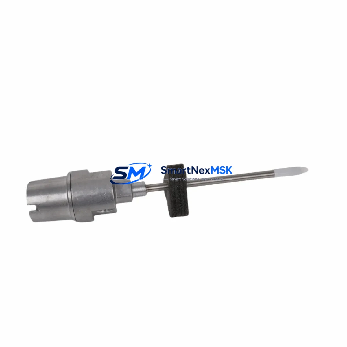
Bently Nevada 21000-16-10-00-123-03-02 Retrofit-Ready Proximity Probe for 21000 Series Control Systems
The Bently Nevada 21000-16-10-00-123-03-02 is a 16 mm eddy-current proximity probe engineered for direct retrofit into existing Bently Nevada 21000 Series vibration monitoring installations. As legacy machinery protection systems age and OEM support for discontinued probe assemblies becomes increasingly difficult to secure, plant engineers and reliability teams face mounting pressure to source verified replacement components that preserve measurement accuracy, signal chain integrity, and compliance with API 670 machinery protection standards — without triggering a full system overhaul.
This probe is designed to serve as a drop-in replacement for worn, damaged, or end-of-life 21000 Series proximity probes, maintaining full compatibility with the 3300 XL 8mm and 3300 XL 11mm extension cable assemblies, the 3300 RAM proximitor/seismic transducer, and the 3500/42M Proximitor/Seismic Monitor module. When integrated into a 3500 Series rack, the 21000-16-10-00-123-03-02 interfaces directly with the 3500/20 rack interface module and communicates over the standard Bently Nevada System 1 data acquisition platform, preserving existing trend data continuity and alarm setpoint configurations without requiring re-commissioning of the full monitoring loop.
Upgrade Compatibility Table
| Parameter | Detail |
|---|---|
| SKU / Part Number | 21000-16-10-00-123-03-02 |
| Brand | Bently Nevada |
| Series | 21000 Series |
| Probe Diameter | 16 mm |
| Cable Length | 10 ft (3.05 m) integral cable |
| Output Sensitivity | 200 mV/mil (7.87 V/mm) nominal |
| Bias Voltage | −10.0 VDC nominal at 50 mil (1.27 mm) gap |
| Compatible Proximitor | 3300 RAM, 3300 XL, 3500/42M |
| Compatible Extension Cable | 3300 XL 8mm / 11mm extension assemblies |
| Compatible Monitor Module | 3500/42M Proximitor/Seismic Monitor |
| Rack Interface | 3500/20 Rack Interface Module |
| Communication Protocol | Bently Nevada System 1 / Modbus RTU (via gateway) |
| Installation Type | Direct retrofit — no bracket modification required |
| Commissioning Requirement | Gap voltage verification; no full re-calibration required |
| Warranty | 12 Months |
Retrofit Planning for Existing Automation Systems
Successful integration of the 21000-16-10-00-123-03-02 into a running plant environment requires a structured pre-installation review. Before removing the failed or degraded probe, technicians should document the existing gap voltage reading at the 3300 RAM proximitor output — typically between −9.5 VDC and −10.5 VDC for a healthy 50 mil air gap — and record the current vibration baseline and alarm setpoints stored in the 3500/42M monitor module. This baseline data is critical for post-installation verification and for confirming that the replacement probe is operating within the original calibration envelope.
Terminal wiring on the 21000 Series probe connector follows the standard Bently Nevada color code: the center conductor carries the RF signal, the shield is grounded at the proximitor end only, and the outer jacket provides mechanical protection. When routing the integral cable through existing conduit or cable trays, engineers should verify that the cable is not routed adjacent to high-voltage power conductors or variable-frequency drive (VFD) output cables, as induced noise can corrupt the proximity signal and trigger spurious alarms in the 3500 Series rack.
For installations where the 3300 RAM proximitor is also being replaced as part of a broader upgrade, the 3500/42M Proximitor/Seismic Monitor module should be configured to accept the new probe’s sensitivity factor before the system is returned to service. If the plant is migrating from an older 7200 Series monitoring system to the 3500 platform, the 3500/20 rack interface module will need to be programmed with the correct I/O mapping to ensure that vibration, position, and speed signals are correctly routed to the DCS or safety instrumented system (SIS). In plants using a Honeywell Experion PKS or Emerson DeltaV DCS, the System 1 gateway module handles protocol translation between the Bently Nevada rack and the DCS historian, preserving alarm annunciation and trend archiving without interruption.
Where I/O expansion is required — for example, when adding radial vibration monitoring to a previously unmonitored bearing location — the 3500/42M module supports up to four channel pairs per card, and additional 3500 Series I/O modules can be added to the same 19-inch rack without requiring a new rack power supply, provided the 3500/15 power supply module’s total load budget is not exceeded. For installations requiring keyphasor reference signals, the 3500/25 keyphasor module should be verified for compatibility with the existing tachometer probe and target wheel configuration before the retrofit is finalized.
Downtime Control During System Migration
Minimizing unplanned downtime is the primary operational constraint in any proximity probe replacement on a running machine train. The recommended approach is to perform the probe swap during a scheduled maintenance window, with the machine at rest and the 3500 Series rack placed in bypass mode to suppress spurious trip signals during the installation. The 3500/42M monitor module supports a software bypass function accessible through the System 1 software interface, which allows individual channels to be inhibited without affecting the monitoring status of adjacent channels or triggering a rack-level trip.
Before the machine is returned to service, the replacement 21000-16-10-00-123-03-02 probe should be gapped to the manufacturer’s recommended air gap using a non-ferrous feeler gauge, and the output voltage should be verified at the proximitor terminal strip. The measured gap voltage should be logged and compared against the pre-removal baseline. If the gap voltage is within ±0.5 VDC of the original reading, the probe installation is confirmed and the channel bypass can be released. The machine can then be restarted under normal monitoring conditions, with the first 30 minutes of operation used to confirm that vibration trends are tracking within expected limits and that no new alarms have been generated.
For plants where continuous operation is mandatory and a cold shutdown is not possible, a hot-swap procedure can be executed using a spare 3500/42M monitor module pre-configured with the correct channel settings. The spare module is installed in an adjacent rack slot, the probe signal is transferred to the new module, and the original module is removed — all without interrupting the monitoring loop. This approach requires advance preparation of the spare module and coordination with the control room operator to manage alarm inhibit periods, but it eliminates the need for a machine shutdown entirely.
Retrofit Support FAQ
Q1: Is the 21000-16-10-00-123-03-02 a direct replacement for all 21000 Series proximity probes?
The 21000-16-10-00-123-03-02 is a direct replacement for 21000 Series probes with the same 16 mm tip diameter, 10 ft integral cable, and standard sensitivity specification. Probes with different cable lengths (e.g., 5 ft or 15 ft variants) or extended-temperature ratings require verification against the original part number suffix before substitution. Contact our technical team with your original part number for a confirmed cross-reference.
Q2: Do I need to recalibrate the 3500/42M monitor module after replacing the probe?
In most cases, full recalibration is not required if the replacement probe is the same model and the gap voltage is set to the original specification. However, the channel’s OK limit and alarm setpoints should be verified in the System 1 software after installation, and a functional test of the OK relay output should be performed to confirm that the monitor is correctly detecting the probe’s presence and signal integrity.
Q3: What wiring checks should be performed before powering up the new probe?
Before energizing the proximitor, verify that the probe cable shield is grounded at the proximitor end only (not at the probe end), that the center conductor is securely terminated at the proximitor input terminal, and that the cable is routed away from high-voltage or VFD conductors. Measure the cable insulation resistance between the center conductor and shield to confirm there is no damage to the integral cable from the installation process.
Q4: What does the 12-month warranty cover?
The 12-month warranty covers manufacturing defects, premature failure under normal operating conditions, and out-of-specification performance at the time of delivery. Each unit undergoes pre-shipment functional testing, including gap voltage output verification and cable continuity check, before dispatch. Warranty claims are supported by our technical team with replacement or repair at no additional cost within the warranty period. Damage resulting from incorrect installation, overvoltage, or mechanical impact is not covered.
© 2026 SMARTNEXMSK. All rights reserved.
Original Source: https://smartnexmsk.com
Contact: [email protected] | +86 18259474341



