
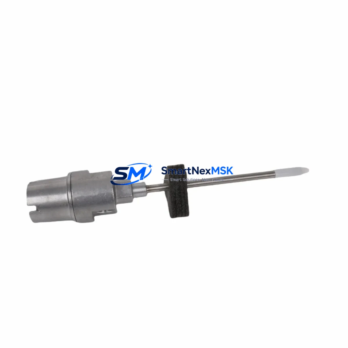
Bently Nevada 21000-16-10-15-088-03-02 Retrofit-Ready Proximity Probe for 21000 Series Control Systems
The Bently Nevada 21000-16-10-15-088-03-02 is a precision eddy-current proximity probe assembly engineered for seamless integration into legacy and modernized rotating machinery protection systems. Designed as a direct retrofit replacement within the Bently Nevada 21000 Series platform, this probe delivers reliable shaft displacement and vibration measurement in turbines, compressors, pumps, and other critical rotating equipment where continuous uptime is non-negotiable.
As industrial facilities face increasing pressure to extend the service life of existing control infrastructure while meeting modern reliability standards, the 21000-16-10-15-088-03-02 provides a validated upgrade path. Its 16 mm armored cable construction, standardized connector interface, and calibrated sensitivity range allow maintenance engineers to execute a drop-in replacement without modifying existing conduit runs, junction boxes, or monitor rack wiring. This significantly reduces the engineering hours required during planned outages and minimizes the risk of introducing wiring errors during a rushed turnaround.
When planning a retrofit around this probe, engineers should verify several critical parameters before committing to installation. Power supply capacity at the proximitor or extension cable junction must be confirmed against the 21000 Series specification — typically –24 VDC with a defined current draw per channel. Terminal block wiring at the field junction box should be inspected for correct polarity and shield grounding, as improper grounding is a leading cause of noise-induced false trips in eddy-current systems. The backplane interface within the monitor rack, whether a 3300 Series or TDXnet rack, must be confirmed compatible with the probe’s output voltage range (typically –2 VDC to –18 VDC at the proximitor output). Module addressing within the rack configuration should be reviewed in the System 1 or Rack Configuration Software to ensure the channel assignment matches the physical probe location. Program logic in the associated safety or condition monitoring controller — often a Bently Nevada 3500 Series rack or a third-party DCS — should be validated to confirm that trip setpoints, alert thresholds, and gap voltage references remain appropriate for the replacement probe’s calibration curve.
HMI display screens tied to the vibration monitoring loop should be reviewed to confirm that engineering unit scaling and alarm annunciation remain consistent after the swap. Communication links between the monitor rack and the plant DCS — whether via Modbus RTU, FOUNDATION Fieldbus, or a 4–20 mA hardwired signal — should be verified end-to-end before returning the machine to service. Field commissioning should include a static gap check using a calibrated oscilloscope or the Bently Nevada proximitor test kit, followed by a dynamic run-up to confirm that the probe output tracks shaft displacement within the expected range across the full operating speed envelope.
Upgrade Compatibility Table
| Parameter | Detail |
|---|---|
| SKU / Part Number | 21000-16-10-15-088-03-02 |
| Brand | Bently Nevada |
| Series Compatibility | Bently Nevada 21000 Series |
| Monitor Rack Compatibility | 3300 Series, 3500 Series, TDXnet Rack |
| Cable Length / Type | 16 mm armored extension cable |
| Output Voltage Range | –2 VDC to –18 VDC (proximitor output) |
| Supply Voltage | –24 VDC nominal |
| Installation Type | Direct drop-in retrofit; no conduit modification required |
| Communication Compatibility | Modbus RTU, 4–20 mA, FOUNDATION Fieldbus (via monitor rack) |
| Replacement Recommendation | Direct replacement for discontinued 21000-16-10-15-088-03-02 units |
| Commissioning Requirement | Static gap check + dynamic run-up verification |
| Warranty | 12-Month Warranty included |
| Origin | China (CN) |
| Shipping | Fast global shipping; export documentation available |
Retrofit Planning for Existing Automation Systems
A successful retrofit of the 21000-16-10-15-088-03-02 into an aging machinery protection system requires a structured approach that accounts for every component in the measurement chain. The probe itself is only one element of a larger signal path that typically includes a Bently Nevada 330130 or 330180 proximitor (extension driver), a shielded coaxial extension cable, a field junction box with terminal strips, and a monitor module seated in a 3500 Series or 3300 Series rack. Each of these components must be assessed for compatibility and condition before the replacement probe is installed.
In facilities running older 3300 Series racks, the transition to a 3500 Series rack is often undertaken in parallel with a probe replacement campaign. The 3500/40M proximitor I/O module, the 3500/42M proximitor I/O module, and the 3500/22M transient data interface are commonly encountered during such upgrades. Engineers should confirm that the rack’s power supply module — such as the 3500/15 power supply — has sufficient capacity to support the additional channel load if I/O expansion is part of the scope. Where the existing rack uses a 3300/16 monitor, the output signal wiring to the DCS marshalling cabinet must be re-mapped to match the 3500 Series terminal assignments.
For facilities integrating the replacement probe into a broader DCS migration — for example, moving from a legacy Honeywell TDC 3000 or Foxboro I/A Series platform to a modern DeltaV or ABB 800xA system — the 4–20 mA output from the Bently Nevada monitor rack provides a hardware-agnostic interface that simplifies the transition. Modbus RTU communication cards within the 3500 rack can be configured to expose vibration and position data to the new DCS without requiring changes to the field wiring. Where FOUNDATION Fieldbus is the target protocol, a gateway module may be required to bridge the rack’s serial output to the fieldbus segment.
I/O expansion during a control cabinet upgrade may also involve adding a Bently Nevada 3500/64M process variable monitor or a 3500/70M communications gateway to support additional measurement points brought online as part of the modernization. Programming cable access — typically via a Bently Nevada 3500 configuration cable connected to a laptop running Rack Configuration Software — is required to update channel parameters, gap voltage references, and alarm setpoints after the new probe is installed and gapped.
Downtime Control During System Migration
Minimizing unplanned downtime during a proximity probe replacement is a primary concern for maintenance teams operating in continuous-process environments. The 21000-16-10-15-088-03-02 is stocked and available for immediate dispatch, which eliminates the lead-time risk that often forces extended outages when sourcing discontinued or long-lead components through OEM channels.
To protect original program logic during the replacement, the existing rack configuration file should be exported from the Rack Configuration Software and archived before any hardware changes are made. This backup ensures that channel parameters, trip multiplier settings, and Keyphasor assignments can be restored exactly if a configuration error occurs during commissioning. Where the monitor rack is connected to a safety instrumented system, the SIS bypass procedure should be activated and documented before the probe is disconnected, and the bypass should remain in place until the replacement probe has been verified in service.
Field continuity can be maintained during the probe swap by using a temporary resistive load to simulate the probe impedance at the proximitor input, allowing the monitor channel to remain in a defined state rather than generating a fault trip that could cascade to other protective functions. Once the replacement probe is installed and the gap is set to the specified voltage (typically –10 VDC ±0.5 VDC at the design gap), the temporary load is removed and the channel is returned to normal monitoring mode. A final review of the System 1 trend data or the DCS historian confirms that the replacement probe is tracking shaft position consistently with the pre-outage baseline.
Retrofit Support FAQ
Q: Is the 21000-16-10-15-088-03-02 a direct replacement for the original Bently Nevada part?
A: Yes. This unit is a direct retrofit replacement for the original 21000-16-10-15-088-03-02 proximity probe assembly. It maintains the same cable length, connector type, sensitivity, and output voltage range, allowing installation without modifications to existing conduit, junction box wiring, or monitor rack configuration.
Q: What commissioning steps are required after installation?
A: After mechanical installation, perform a static gap check using a calibrated oscilloscope or the Bently Nevada proximitor test kit to confirm the output voltage is within the specified range at the design gap distance. Follow with a dynamic run-up to verify that the probe tracks shaft displacement correctly across the operating speed range. Update and archive the rack configuration file after confirming all parameters are correct.
Q: How do I verify wiring compatibility with my existing terminal block layout?
A: Compare the probe connector pinout and cable shield grounding scheme against the existing junction box terminal drawings. The 21000 Series uses a standardized coaxial signal path; confirm that the center conductor, outer shield, and supply voltage connections match the original wiring diagram. Incorrect shield grounding is the most common source of noise issues after a probe replacement.
Q: What warranty coverage is included?
A: Every 21000-16-10-15-088-03-02 unit supplied by SMARTNEXMSK includes a 12-month warranty covering manufacturing defects and functional failures under normal operating conditions. Pre-shipment testing is performed on each unit to verify output voltage, cable continuity, and connector integrity before dispatch.
© 2026 SMARTNEXMSK. All rights reserved.
Original Source: https://smartnexmsk.com
Contact: [email protected] | +86 18259474341



