
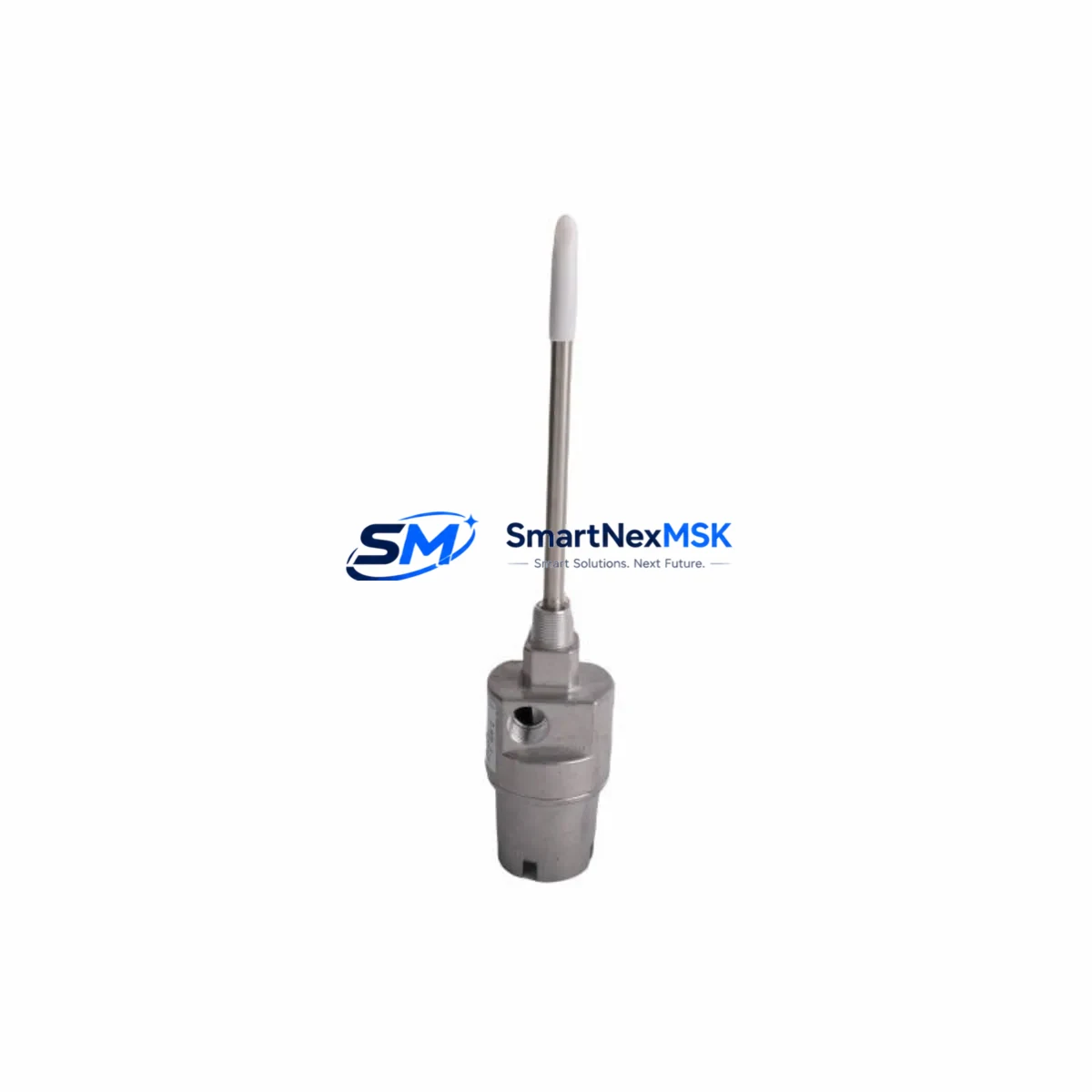
Bently Nevada 21000-16-10-15-108-03-02 Maintenance-Ready Spare for 21000 Series Automation
The Bently Nevada 21000-16-10-15-108-03-02 is an original proximity probe housing assembly engineered for continuous-duty industrial vibration monitoring systems. Designed as a direct maintenance spare within the Bently Nevada 21000 Series platform, this component supports rapid field replacement in rotating machinery protection systems — including steam turbines, gas compressors, centrifugal pumps, and large induction motors. Sourced from verified supply channels, each unit is inspection-tested prior to dispatch and backed by a 12-month warranty covering manufacturing defects and functional performance.
For maintenance engineers managing critical rotating assets, unplanned downtime caused by a failed proximity probe assembly can cascade into production losses within minutes. Stocking the 21000-16-10-15-108-03-02 as a ready spare eliminates the lead-time risk associated with OEM procurement cycles. The housing assembly maintains the precise dimensional tolerances required for eddy-current gap calibration, ensuring that replacement does not require full system recalibration when installed correctly against the original mounting specification.
Procurement engineers sourcing this part for MRO inventory should confirm compatibility with the installed 3300 XL or 7200 Series proximitor/extension cable system. The probe housing interfaces directly with the proximitor sensor and must be matched to the correct gap voltage range — typically –10 VDC at the calibrated gap — to maintain system accuracy within ±0.5% of full scale. Mismatched housing geometry or non-original components can introduce signal drift that triggers false alarms in the vibration monitoring rack.
Spare Maintenance Table
| Parameter | Specification |
|---|---|
| Part Number | 21000-16-10-15-108-03-02 |
| Brand | Bently Nevada |
| Series | 21000 Series |
| Product Type | Proximity Probe Housing Assembly |
| Sensing Technology | Eddy-Current (Non-Contact) |
| Nominal Gap Voltage | –10 VDC (at calibrated gap) |
| Compatible Proximitor | 3300 XL / 7200 Series Proximitor Sensor |
| Cable Interface | Extension Cable (armored, matched impedance) |
| Installation Environment | Industrial — turbine halls, compressor stations, pump rooms |
| Mounting | Threaded housing, per OEM bracket specification |
| Origin | United States |
| Condition | Original Spare — New / Tested |
| Warranty | 12 Months (manufacturing defects & functional performance) |
| Pre-Shipment Test | Functional inspection and continuity check |
| Lead Time | In-stock — ships within 1–3 business days |
Maintenance Planning for Continuous Operation
When replacing the 21000-16-10-15-108-03-02 during a planned outage or emergency shutdown, maintenance teams should treat the intervention as an opportunity for a broader control-loop inspection. The proximity probe housing does not operate in isolation — its signal integrity depends on the condition of several interconnected components that are subject to the same thermal cycling, vibration fatigue, and environmental exposure.
Begin by inspecting the extension cable connecting the probe to the proximitor. Armored extension cables in the 21000 Series are rated for specific lengths and impedance values; a cable with damaged shielding or corroded connectors will introduce noise into the gap voltage signal even with a new probe housing installed. Simultaneously, verify the proximitor sensor (such as the 3300 XL 8mm proximitor) for output voltage stability — a drifting proximitor can mask or mimic probe housing failure.
At the monitoring rack level, inspect the 3500 Series vibration monitoring rack input cards and their terminal blocks. Loose terminal connections on the I/O module are a common source of intermittent alarms that are incorrectly attributed to probe failure. If the system uses a 3500/42M Proximitor/Seismic Monitor or similar rack card, confirm that the channel configuration matches the replacement probe’s sensitivity factor (typically 7.87 V/mm or 200 mV/mil).
For installations where the probe feeds into a DCS or safety instrumented system (SIS), check the signal isolator or barrier — particularly Zener barriers or galvanic isolators used in hazardous-area installations — to ensure they have not degraded. A faulty isolator will corrupt the 4–20 mA or voltage signal downstream regardless of probe condition. Also review the power supply module feeding the proximitor; the 3300 XL system requires a stable –24 VDC supply, and a sagging power rail will cause the entire probe loop to read incorrectly.
Where the vibration signal connects to a PLC analog input module, verify the input card’s channel calibration and confirm that the engineering unit scaling has not been altered. In older systems, it is also advisable to inspect the junction box and any terminal strips in the field wiring run for moisture ingress, which is a leading cause of insulation resistance failure in probe circuits. Completing this checklist during a single maintenance window significantly reduces the probability of a repeat callout.
Site Replacement Workflow
The 21000-16-10-15-108-03-02 is designed as a like-for-like replacement for the original OEM housing assembly. No firmware changes, rack reconfiguration, or software updates are required when replacing a failed unit with this spare, provided the replacement is installed to the same gap distance and the extension cable is undamaged.
Step 1 — Isolation: Inhibit the vibration channel at the monitoring rack (3500 Series or equivalent) to prevent a spurious trip during probe removal. Document the current gap voltage reading before disconnecting.
Step 2 — Removal: Disconnect the extension cable at the probe end. Unthread the housing assembly from the mounting bracket. Inspect the bracket and target area for wear, corrosion, or mechanical damage that may have contributed to the original failure.
Step 3 — Installation: Thread the 21000-16-10-15-108-03-02 into the bracket. Set the gap distance per the OEM specification (typically 1.0–1.5 mm for standard 8mm probes). Reconnect the extension cable, ensuring the connector is fully seated and the locking collar is secure.
Step 4 — Verification: Re-enable the channel and confirm the gap voltage is within the calibrated range (–10 VDC ±0.5 V at nominal gap). Compare the live vibration reading against adjacent channels and historical baseline data to confirm normal operation before releasing the machine to service.
This workflow minimizes downtime to under 30 minutes for a prepared maintenance team and eliminates the need for a full system recalibration, preserving the existing alarm and danger setpoints.
Spare Parts Support FAQ
Q1: Is the 21000-16-10-15-108-03-02 compatible with both the 3300 XL and 7200 Series proximitor systems?
Yes. The 21000 Series probe housing assemblies are designed to interface with Bently Nevada’s standard proximitor product lines, including the 3300 XL 8mm and 7200 Series proximitors, provided the extension cable length and impedance are matched to the system specification. Always verify the sensitivity factor (mV/mil or V/mm) matches the rack card configuration before installation.
Q2: What pre-shipment testing is performed on this spare?
Each unit undergoes a functional inspection including dimensional verification of the housing geometry, continuity check of the internal coil circuit, and visual inspection for physical damage. Units that do not meet specification are quarantined and not dispatched. A test record is available upon request for quality-critical applications.
Q3: How should this spare be stored if not immediately installed?
Store in the original packaging in a dry, temperature-controlled environment (5–40°C, <85% RH non-condensing). Avoid storage near strong magnetic fields or sources of mechanical vibration. Inspect the connector and housing threads annually if held in long-term MRO inventory. The 12-month warranty period begins from the date of shipment.
Q4: Can this part replace discontinued or end-of-life Bently Nevada probe assemblies in the same series?
In many cases, yes. The 21000 Series housing assemblies share a common mechanical interface across multiple sub-variants. Compatibility depends on the specific mounting bracket geometry, target material, and gap range of the installed system. Contact our technical team with your existing part number and installation drawing for a compatibility confirmation before ordering for a critical application.
© 2026 SMARTNEXMSK. All rights reserved.
Original Source: https://smartnexmsk.com
Contact: [email protected] | +86 18259474341



