
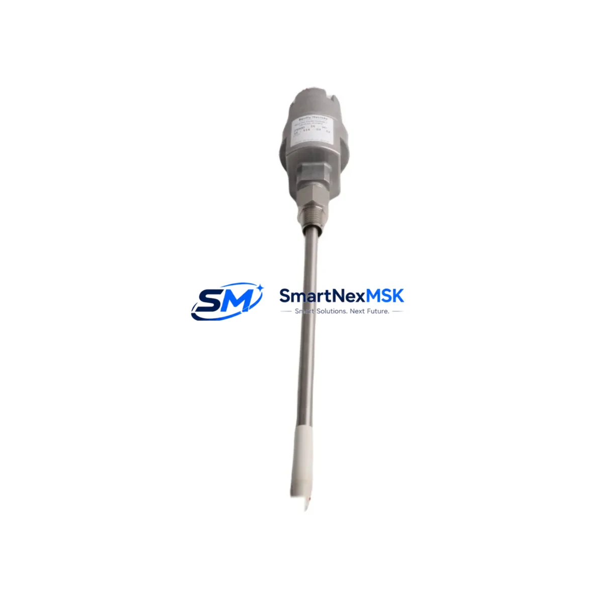
Bently Nevada 21000-28-05-15-50-03-02 Retrofit-Ready Proximity Probe for 21000 Series Control Systems
The Bently Nevada 21000-28-05-15-50-03-02 is a high-precision eddy-current proximity probe engineered for continuous vibration and position monitoring in rotating machinery. As legacy 21000 Series installations approach end-of-life or face discontinued spare-parts availability, this retrofit-ready unit provides a verified drop-in replacement path that preserves existing wiring, conduit runs, and Bently Nevada 3300 Series or 7200 Series signal conditioning infrastructure. Whether you are executing a planned outage upgrade, responding to an unplanned probe failure, or modernizing a turbine protection panel, the 21000-28-05-15-50-03-02 delivers the dimensional accuracy, gap voltage linearity, and sensitivity coefficient required by the original system specification.
Industrial facilities running GE, Siemens, or Emerson turbine control platforms frequently rely on Bently Nevada proximity systems as the primary vibration input to their machinery protection logic. When a probe in this family fails or is flagged during a predictive maintenance inspection, the replacement window is narrow. This unit ships pre-tested against Bently Nevada factory calibration standards, with a documented sensitivity of 7.87 V/mm (200 mV/mil) and a linear range compatible with the standard 21000 Series extension cable and proximitor driver combination. Procurement teams can confirm interchangeability against the original bill of materials without requiring a re-engineering review.
Upgrade Compatibility Table
| Parameter | Detail |
|---|---|
| SKU / Part Number | 21000-28-05-15-50-03-02 |
| Brand / OEM | Bently Nevada |
| Series Compatibility | Bently Nevada 21000 Series |
| Signal Conditioning | Compatible with 3300 Series Proximitor, 7200 Series Proximitor |
| Sensitivity | 7.87 V/mm (200 mV/mil), ±0.5% |
| Probe Body Diameter | 8 mm (standard) |
| Cable Length | 5 m integral cable (matched to extension cable requirement) |
| Thread / Mounting | M10 × 1 (standard 21000 Series mount) |
| Temperature Range | −35 °C to +177 °C (probe tip) |
| Installation Interface | Drop-in; no conduit or junction box modification required |
| Communication / Protocol | Analog 4–20 mA / voltage output via Proximitor; no fieldbus change |
| Replacement Recommendation | Direct replacement for discontinued 21000-28-05-15-50-03-02 variants |
| Commissioning Note | Verify gap voltage at 1.0 mm (−10.0 V nominal) before returning to service |
| Warranty | 12-Month Warranty — covers manufacturing defects and calibration drift |
Retrofit Planning for Existing Automation Systems
A successful retrofit of the 21000-28-05-15-50-03-02 begins well before the maintenance window opens. The first step is a power budget review of the existing Proximitor driver — typically a Bently Nevada 3300 XL 8mm Proximitor or a 7200 Series Proximitor — to confirm that the bias supply voltage (−24 VDC nominal) remains within specification after years of service. Aging power supply modules in the machinery protection rack can introduce voltage droop that shifts the probe’s operating point outside its linear range, producing false vibration readings even with a new probe installed.
Terminal wiring should be documented before disconnection. The 21000 Series uses a three-conductor shielded cable arrangement (drive, return, shield) that must be maintained through the extension cable junction. If the existing Bently Nevada 330130 extension cable shows insulation degradation or connector corrosion, replacement of the extension cable in the same maintenance window eliminates a common source of post-retrofit signal noise. The junction box connector type — typically a Bently Nevada standard bayonet or threaded coupling — should be inspected and cleaned before the new probe is installed.
For facilities that have migrated their machinery protection system to a Bently Nevada System 1 software platform or are interfacing with a GE Mark VIe or Emerson Ovation DCS, the analog output from the Proximitor feeds directly into the I/O module without protocol conversion. However, if the control system has been upgraded to accept PROFIBUS or Modbus RTU inputs from a gateway device, the gateway configuration must be verified to ensure the new probe’s sensitivity coefficient is correctly entered. Incorrect scaling at the gateway will cause the DCS historian to log erroneous vibration amplitude values, which can trigger nuisance trips or — more dangerously — mask real machinery faults.
Backplane and rack considerations are minimal for a like-for-like probe swap, but facilities planning a broader upgrade should note that the Bently Nevada 3500 Series rack system offers a migration path from 21000 Series probes with adapter modules that preserve existing conduit entries. If the upgrade scope includes adding a Bently Nevada 3500/42M Proximitor Monitor or a 3500/40M Proximitor Monitor, the I/O channel mapping in the protection logic must be reviewed and the associated HMI faceplates updated to reflect the new module addresses. Operators should be briefed on any changes to alarm setpoint displays before the system is returned to automatic protection mode.
Programming compatibility is straightforward for a probe-only replacement: no PLC ladder logic or function block changes are required. However, if the site uses a Rockwell Automation ControlLogix or Allen-Bradley PLC-5 as the supervisory controller receiving vibration data from the Bently Nevada rack via a Data Highway Plus or EtherNet/IP link, the tag database should be audited to confirm that the vibration channel tag still maps to the correct rack slot after any hardware rearrangement. A pre-commissioning loop check — driving the probe gap with a calibrated target and verifying the engineering-unit value at the HMI — takes less than 30 minutes and eliminates the most common source of post-retrofit commissioning delays.
Downtime Control During System Migration
Minimizing unplanned downtime during a proximity probe replacement requires a structured bypass and handover sequence. Before isolating the faulty channel, confirm with the control room that the machinery protection system can be placed in a voted or bypassed state for the affected channel without disabling overall trip protection. Most Bently Nevada 3500 Series and legacy 21000 Series installations support a 2-out-of-3 voting architecture that allows one channel to be taken out of service while the remaining channels maintain full protection coverage.
The original probe should be removed only after the replacement unit has been staged at the work site with its gap voltage pre-verified on a bench fixture. This eliminates the risk of discovering a calibration issue after the machine is already in a partially unprotected state. Once the new 21000-28-05-15-50-03-02 is installed and the gap set to the target value (typically 1.0 mm for an 8 mm probe on a steel target), the channel should be re-enabled in the protection rack and the output monitored for at least five minutes at operating speed before the bypass is removed.
Original program logic — including trip setpoints, alarm thresholds, and time-delay settings stored in the Bently Nevada rack configuration or the supervisory PLC — is not affected by a probe replacement and does not require re-entry. Configuration files should nonetheless be backed up to a portable storage device before the maintenance window begins, as a precaution against accidental parameter loss during rack power cycling. This practice also supports the site’s change management documentation requirements and simplifies the post-maintenance audit trail.
Retrofit Support FAQ
Q1: Is the 21000-28-05-15-50-03-02 a direct drop-in replacement for the original Bently Nevada part?
Yes. This unit is manufactured to the same dimensional and electrical specification as the original 21000-28-05-15-50-03-02. It uses the same M10 × 1 thread, the same 8 mm probe body, and the same 5 m integral cable length, and it is calibrated to the standard 7.87 V/mm sensitivity. No adapter, re-wiring, or reconfiguration of the Proximitor driver is required for a like-for-like swap.
Q2: What commissioning checks are required after installation?
After mechanical installation, set the probe gap to the value specified in the original machinery datasheet (typically 1.0 mm for steel targets). Measure the Proximitor output voltage and confirm it falls within the linear range (approximately −10.0 V ± 0.5 V at 1.0 mm gap). Perform a loop check by verifying the engineering-unit reading at the DCS or HMI matches the expected value. Document the as-found and as-left gap measurements in the maintenance record before returning the channel to service.
Q3: How is wiring compatibility confirmed for older installations?
The 21000 Series uses a standardized three-conductor shielded cable arrangement. Verify that the existing extension cable — typically a Bently Nevada 330130 or equivalent — is undamaged and that the connector at the junction box is clean and fully seated. If the extension cable is more than ten years old or shows visible insulation damage, replacement in the same maintenance window is strongly recommended to avoid post-retrofit signal integrity issues.
Q4: What does the 12-month warranty cover?
The 12-month warranty covers manufacturing defects, calibration drift beyond the published specification, and connector or cable integrity failures under normal operating conditions. Each unit is shipped with a test report confirming sensitivity, linearity, and insulation resistance. Warranty claims are processed with return of the defective unit and the original test report. Units showing evidence of mechanical damage from improper installation or operation outside the rated temperature range are not covered.
© 2026 SMARTNEXMSK. All rights reserved.
Original Source: https://smartnexmsk.com
Contact: [email protected] | +86 18259474341



