
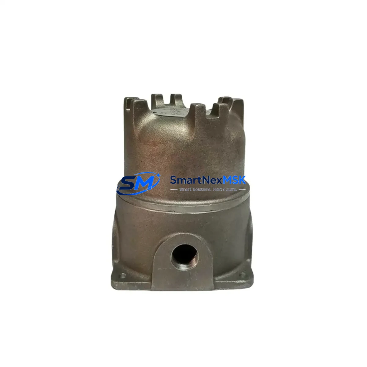
Bently Nevada 21022-00-00-017-00 Maintenance-Ready Spare for 3300 Series Automation
The Bently Nevada 21022-00-00-017-00 is a dual-channel axial proximity probe housing engineered for the 3300 Series vibration monitoring system — one of the most widely deployed machinery protection platforms in rotating equipment applications worldwide. For maintenance engineers managing turbines, compressors, pumps, and gearboxes, this component sits at the heart of continuous shaft position and vibration measurement. When this housing fails or degrades, the entire monitoring loop is compromised, creating an unacceptable risk of undetected machinery fault and unplanned shutdown.
Sourced as an original spare, the 21022-00-00-017-00 is stocked and tested prior to dispatch, ensuring that replacement units arrive ready for immediate installation. Each unit undergoes pre-shipment functional verification and ships with a 12-month warranty covering manufacturing defects and performance conformance to Bently Nevada 3300 Series specifications.
Spare Maintenance Table
| Parameter | Specification / Value |
|---|---|
| Part Number | 21022-00-00-017-00 |
| Brand | Bently Nevada |
| Series | 3300 Series Vibration Monitoring System |
| Component Type | Proximity Probe Housing (Dual Axial) |
| Compatibility | Bently Nevada 3300 Series monitors, 3300/16 and 3300/20 rack modules |
| Application | Shaft axial position, radial vibration, differential expansion measurement |
| Installation Environment | Industrial plant floor, turbine hall, compressor skid, rotating machinery enclosure |
| Mounting | Standard Bently Nevada probe housing thread and bracket interface |
| Signal Type | Eddy-current proximity, compatible with 3300 XL transducer driver |
| Operating Temperature | -35°C to +120°C (probe tip environment) |
| Condition | Original spare — new or fully refurbished to OEM standard |
| Pre-shipment Testing | Functional verification performed before dispatch |
| Warranty | 12 months from date of shipment |
| Lead Time | In-stock; same-day or next-business-day dispatch available |
| Origin | USA (Bently Nevada / Baker Hughes) |
Maintenance Planning for Continuous Operation
Replacing the 21022-00-00-017-00 probe housing is rarely an isolated task. A disciplined maintenance engineer will treat this replacement as an opportunity to audit the entire vibration monitoring loop and adjacent control cabinet components. During the same maintenance window, it is best practice to inspect the 3300 XL transducer driver (typically the 330180 or 330130 series) for signal drift or connector corrosion, as probe housing wear often correlates with driver degradation caused by cable impedance mismatch.
The interconnect cable assembly — commonly the 330130-080-00-00 or equivalent armored extension cable — should be checked for jacket integrity, shield continuity, and connector seating. A compromised cable will produce erratic gap voltage readings even with a new housing installed. Similarly, the proximitor sensor mounted in the field junction box should be verified for output voltage linearity across the full measurement range.
Within the control rack, the 3300/16 or 3300/20 monitor module should be inspected for alarm setpoint integrity and relay output function. If the plant runs a dual-channel configuration, both channels should be re-zeroed after housing replacement. The rack power supply module — often a 3300/05 or equivalent — should be load-tested to confirm stable ±24 VDC output, as power ripple is a common source of false vibration alarms.
For plants integrating Bently Nevada data into a DCS or safety system, the 4–20 mA output module and associated signal isolator (such as a Phoenix Contact or Pepperl+Fuchs barrier) should be verified for loop integrity. The terminal block assemblies within the marshalling cabinet — particularly those carrying the proximitor output signal — should be torque-checked and inspected for oxidation. Loose terminations at this stage will introduce noise that mimics real vibration events.
If the plant uses a System 1 Evolution or System 1 Optimizer software platform for condition monitoring, the channel configuration should be updated to reflect the new probe gap setting after installation. Finally, any overspeed detection module or thrust position monitor sharing the same rack should be functionally tested before returning the machine to service, as these safety-critical channels may have been affected by the maintenance outage.
Site Replacement Workflow
Step 1 — Isolation and Permit: Obtain a Permit to Work and isolate the affected monitoring channel at the rack. Do not de-energize the entire rack if other channels are protecting running machinery.
Step 2 — Gap Voltage Baseline: Record the existing gap voltage on the channel being replaced. This provides a reference for post-installation verification.
Step 3 — Housing Removal: Disconnect the extension cable at the probe housing. Remove the housing from the bracket, noting the thread engagement depth for reinstallation reference.
Step 4 — New Housing Installation: Install the 21022-00-00-017-00 replacement housing to the same thread depth. Reconnect the extension cable and verify connector seating and locking.
Step 5 — Gap Setting: With the shaft stationary, adjust probe gap to achieve the target gap voltage specified in the machine’s vibration monitoring datasheet (typically –10 VDC ±0.5 V for standard 3300 XL systems).
Step 6 — Functional Verification: Confirm gap voltage, alarm setpoints, and relay outputs at the monitor module. Clear any latched alarms and verify the channel returns to normal status.
Step 7 — Return to Service: Document the replacement in the maintenance management system (CMMS), update the spare parts inventory, and confirm the next planned inspection interval.
This workflow minimizes downtime to a single channel isolation window — typically 2 to 4 hours for a prepared maintenance team — and avoids the extended outage associated with full rack replacement or unplanned failure response.
Spare Parts Support FAQ
Q1: Is the 21022-00-00-017-00 a direct drop-in replacement for the original Bently Nevada housing?
Yes. The replacement unit conforms to the original OEM dimensional and electrical specifications for the 3300 Series probe housing interface. No modification to the bracket, cable, or monitor configuration is required beyond re-setting the probe gap voltage after installation.
Q2: What is the recommended spare parts stocking strategy for this component?
For plants with four or more 3300 Series monitoring channels, we recommend holding a minimum of two 21022-00-00-017-00 housings in the on-site spare parts store. Critical machinery applications — such as main steam turbines or high-pressure compressors — warrant a dedicated hot spare kept in the control room for immediate deployment.
Q3: How is compatibility verified before shipment?
Each unit is cross-referenced against the Bently Nevada 3300 Series bill of materials and subjected to pre-shipment functional testing including gap voltage linearity check and connector integrity verification. A test report is available upon request for quality-critical applications.
Q4: What does the 12-month warranty cover?
The warranty covers manufacturing defects, dimensional non-conformance, and failure to meet 3300 Series electrical performance specifications under normal operating conditions. It does not cover damage resulting from incorrect installation, mechanical impact, or operation outside the specified environmental range. Warranty claims are processed within 5 business days of receipt of the returned unit.
© 2026 SMARTNEXMSK. All rights reserved.
Original Source: https://smartnexmsk.com
Contact: [email protected] | +86 18259474341



