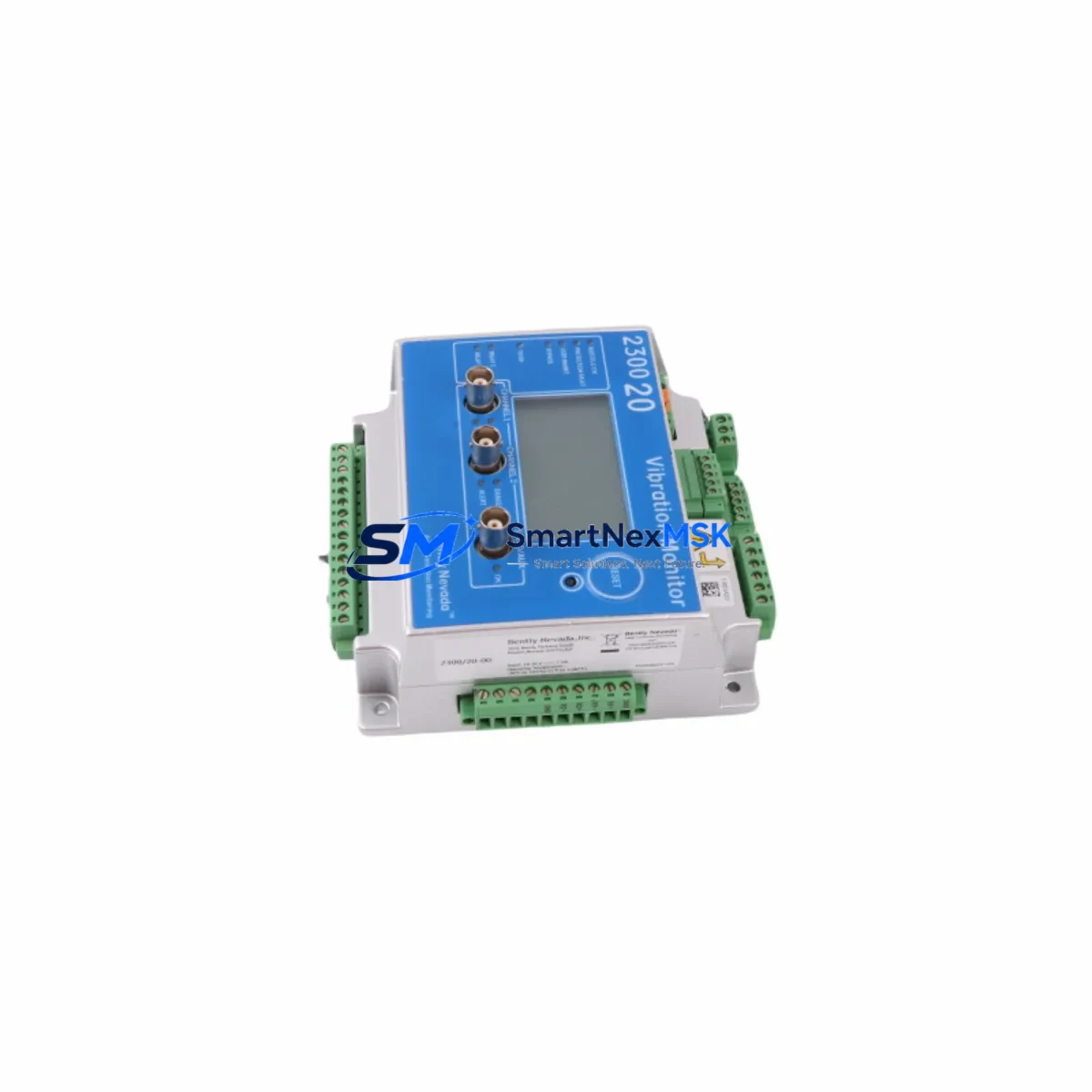
Bently Nevada 2300/20-00 Retrofit-Ready Vibration Monitor: Compatible Upgrade for 3300 Proximity Series Control Systems
The Bently Nevada 2300/20-00 is a dual-channel vibration monitor engineered for seamless integration into legacy 3300 Proximity Series machinery protection systems. As original equipment manufacturers phase out older monitoring hardware, the 2300/20-00 has become a critical retrofit solution for facilities operating rotating machinery — including turbines, compressors, pumps, and gearboxes — where continuous vibration surveillance is non-negotiable. This unit provides a drop-in upgrade path that preserves existing wiring infrastructure, minimizes engineering rework, and maintains compliance with API 670 machinery protection standards.
For plants running aging 3300 Series racks, sourcing a verified replacement for the 2300/20-00 is often the difference between a planned maintenance window and an unplanned shutdown. SMARTNEXMSK maintains in-stock inventory of this module, fully tested and shipped with a 12-month warranty, supporting both emergency breakdown recovery and scheduled system modernization projects.
Upgrade Compatibility Table
| Parameter | Details |
|---|---|
| SKU / Part Number | 2300/20-00 |
| Brand | Bently Nevada |
| Compatible Series | 3300 Proximity Series Machinery Protection System |
| Channels | Dual-channel vibration monitoring |
| Installation | 3300 Series rack-mount; standard backplane interface |
| Communication Compatibility | Compatible with 3300/20 and 3300/25 rack communication architecture; Modbus RTU/TCP gateway support via 3300/93 module |
| Replacement Recommendation | Direct replacement for discontinued 2300-series vibration monitors in 3300 racks |
| Commissioning Notes | Verify transducer gap voltage (nominal −10.0 VDC), OK relay setpoints, and alert/danger thresholds post-installation |
| Wiring Adaptation | Terminal block pinout compatible with existing 3300 field wiring; confirm shield grounding and loop drawings |
| Warranty | 12-Month Warranty — covers manufacturing defects and functional failure under normal operating conditions |
Retrofit Planning for Existing Automation Systems
Replacing the 2300/20-00 in an operating plant requires a structured approach that accounts for the full scope of the 3300 Proximity Series architecture. The 3300 Series rack typically houses a combination of monitor modules, power supply modules, and a system monitor — all of which must be evaluated before a single module swap is executed.
Begin by auditing the existing rack configuration. The 3300/20 rack accepts up to four monitor modules, and the 2300/20-00 occupies one or two slots depending on channel assignment. Confirm that the 3300/05 power supply module is delivering the correct ±24 VDC rail before installing the replacement unit — an under-voltage condition on the power rail is a common cause of false OK relay trips after module replacement. If the power supply is also aging, proactive replacement of the 3300/05 alongside the 2300/20-00 eliminates a second maintenance event within the same outage window.
Transducer compatibility is the next critical checkpoint. The 2300/20-00 is designed to interface with 3300 XL 8mm proximity probes and extension cables. Verify that the existing probe, extension cable, and proximitor (driver) form a matched set — typically a 3300 XL 8mm probe paired with a 3300 XL proximitor such as the 3300/16-02-01-00. Mismatched probe-driver combinations will produce calibration errors that cannot be corrected through software alone. Document the gap voltage (nominally −10.0 VDC for a 3300 XL system) before removal and verify it is restored within ±0.5 VDC after installation.
For facilities that have integrated the 3300 Series rack into a broader DCS or safety instrumented system, the 2300/20-00 replacement must also account for the 4–20 mA output signals routed to the control room. These analog outputs feed historian systems, DCS input cards, and in some cases, safety logic solvers. Confirm that the replacement module’s output scaling matches the original configuration before re-enabling the analog loops. If the plant uses a 3500 Series rack in parallel for API 670 compliance, cross-check that the 3500/42M or 3500/45 monitor modules are not sharing the same transducer — dual-driver configurations require careful impedance management.
Where the control system includes a GE Speedtronic or Emerson Ovation DCS, the vibration data from the 2300/20-00 is typically hardwired rather than communicated over a fieldbus. However, plants that have partially modernized may route vibration data through a Modbus RTU or Modbus TCP gateway. In these cases, verify that the gateway’s register map is updated to reflect any changes in module slot addressing after the replacement. Communication modules such as the 3300/93 or third-party Modbus converters should be tested for correct data throughput before the unit is returned to service.
I/O documentation is equally important. Retrieve the original loop drawings and confirm terminal assignments for the OK relay, alert relay, danger relay, and buffered output connections. The 2300/20-00 uses a standard 3300 Series terminal block, but field wiring labels may have degraded over years of service. Re-labeling terminals during the replacement is a low-cost step that significantly reduces troubleshooting time in future maintenance cycles. If the plant uses a marshalling cabinet with a 3300 Series I/O termination panel, inspect the ribbon cable connectors for corrosion or mechanical damage before reinstalling.
Downtime Control During System Migration
Minimizing downtime during a 2300/20-00 replacement begins with pre-staging. Before the maintenance window opens, bench-test the replacement module using a signal simulator to verify that both channels respond correctly to simulated gap voltage inputs. Confirm that the OK relay energizes at the correct gap voltage and that alert and danger setpoints can be programmed to match the original configuration. This pre-commissioning step eliminates the most common cause of extended outages: discovering a configuration mismatch after the machine is already offline.
During the swap, follow a defined sequence: isolate the rack from the field by placing the system in bypass mode if the 3300 Series supports it, remove the 2300/20-00 from its slot, install the replacement, and restore field connections in the reverse order of removal. Do not power-cycle the entire rack unless necessary — the 3300 Series is designed to support hot-swap of individual monitor modules, and unnecessary power cycling risks disrupting adjacent modules that are actively monitoring other machine trains.
After installation, perform a full channel check: verify gap voltage on both channels, confirm OK relay status, and check that alert and danger setpoints are correctly loaded. If the plant uses a System 1 condition monitoring platform or a similar historian, verify that data is flowing correctly from the 2300/20-00 to the historian before releasing the machine to operations. Document the as-found and as-left gap voltages, setpoints, and relay states in the maintenance record. This documentation is essential for future troubleshooting and for demonstrating compliance with API 670 requirements during audits.
For plants where continuous operation is mandatory, consider a parallel monitoring strategy: install a temporary portable vibration monitor on the machine train before removing the 2300/20-00, maintain monitoring continuity throughout the swap, and remove the portable unit only after the replacement module has been verified in service. This approach is particularly valuable for critical machines where a protection gap — even brief — is unacceptable.
Retrofit Support FAQ
Q1: Is the 2300/20-00 a direct drop-in replacement for the original module in a 3300 Series rack?
A: Yes. The 2300/20-00 is designed to occupy the same rack slot as the original 2300-series monitor modules in a 3300 Proximity Series rack. Terminal block pinout and backplane interface are compatible. However, you should verify gap voltage, setpoints, and relay configurations after installation, as these parameters are stored in the module and must be re-entered if the replacement unit ships with factory defaults.
Q2: What commissioning steps are required after installing the replacement 2300/20-00?
A: After physical installation, verify transducer gap voltage on both channels (nominal −10.0 VDC for 3300 XL systems), confirm OK relay energization, re-enter alert and danger setpoints to match the original configuration, and verify that 4–20 mA analog outputs are within the expected range at the DCS or historian input. If the module communicates through a Modbus gateway, confirm register mapping and data integrity before returning the machine to service.
Q3: Can the 2300/20-00 be used with proximity probes from other manufacturers?
A: The 2300/20-00 is calibrated for use with Bently Nevada 3300 XL 8mm proximity probe systems. Use with non-Bently Nevada probes or proximitors may result in calibration errors and is not recommended without a full system recalibration. If you are migrating from a different probe system, contact our technical team to confirm compatibility before proceeding.
Q4: What does the 12-month warranty cover?
A: The 12-month warranty covers manufacturing defects and functional failure under normal operating conditions from the date of shipment. Each unit is tested prior to dispatch to verify channel functionality, relay operation, and output accuracy. Warranty claims are supported by our technical team — contact [email protected] with your order reference and a description of the fault.
© 2026 SMARTNEXMSK. All rights reserved.
Original Source: https://smartnexmsk.com
Contact: [email protected] | +86 18259474341