
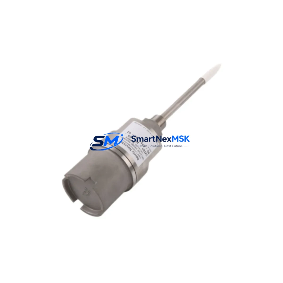
Bently Nevada 24701-28-05-00-025-04-02 Retrofit-Ready Proximity Probe Housing for 24701 Series Control Systems
The Bently Nevada 24701-28-05-00-025-04-02 is a precision-engineered proximity probe housing designed for seamless integration into legacy and modernized vibration monitoring systems. As original 24701 Series components approach end-of-life or become increasingly difficult to source, this retrofit-ready replacement provides a direct, drop-in solution for facilities managing aging turbomachinery protection infrastructure. Whether you are upgrading a 3300 Series rack, migrating to a 3500 Series monitoring platform, or simply restoring a failed channel in an existing control cabinet, this probe housing delivers the dimensional accuracy, electrical compatibility, and field-proven reliability that industrial maintenance teams require.
Engineered to meet the original OEM specifications of the 24701 Series, this housing supports standard 5-metre and 9-metre extension cable configurations and is fully compatible with the Bently Nevada 3300 XL 8mm proximity transducer system. The probe tip geometry, thread pitch, and connector interface are dimensionally identical to the original, eliminating the need for bracket modification or cable re-termination during installation. For facilities operating Bently Nevada 3500/42M or 3500/40M vibration monitor modules, this housing integrates without firmware reconfiguration, preserving existing alarm setpoints, gap voltage calibration, and Keyphasor signal routing.
In retrofit projects involving the replacement of discontinued 24701-28-05-00 variants, engineers must verify power supply capacity within the existing rack. The 3500 Series rack power supply — typically the 3500/15 Power Supply module — must be confirmed to support the additional transducer load if multiple channels are being replaced simultaneously. Terminal block wiring should be cross-referenced against the original loop drawing, paying particular attention to the shield drain wire routing and the barrier ground connection at the I/O module terminal strip. Incorrect shield termination is a leading cause of elevated noise floor readings post-installation and should be verified with a calibrated signal simulator before returning the machine to service.
For sites transitioning from older 3300 Series racks to the 3500 platform, the migration path typically involves replacing the 3300/16 Dual Proximitor Monitor with a 3500/42M Proximitor/Seismic Monitor module, updating the rack backplane interconnect, and re-mapping channel addresses in the System 1 condition monitoring software. The 24701-28-05-00-025-04-02 housing is compatible with both platforms, making it a practical choice for phased migration strategies where not all channels are upgraded simultaneously. During the transition period, mixed-rack configurations are common, and this probe housing eliminates one variable from an otherwise complex changeover.
When planning a control cabinet upgrade that includes this proximity probe housing, the bill of materials typically also encompasses the Bently Nevada 330130 extension cable, the 330180 proximitor sensor, barrier isolators for intrinsically safe zone installations, and DIN rail terminal blocks for signal segregation. In applications where the probe monitors axial position in addition to radial vibration, the associated 3500/45 Position Monitor module must be confirmed as part of the rack configuration. HMI screen templates linked to the original channel tag names should be reviewed and updated in the SCADA or DCS historian to reflect any address changes introduced during the retrofit.
Communication link integrity is another critical checkpoint. Sites using Modbus RTU or Ethernet/IP to transmit vibration data from the 3500 rack to a DCS — such as a Honeywell Experion PKS or an Emerson DeltaV system — should verify that the rack communication gateway module, typically the 3500/92 Communication Gateway, retains its configuration after the channel replacement. In some cases, a firmware update to the gateway is required to support revised channel mapping, and this should be scheduled during the same maintenance window as the probe replacement to minimize total downtime.
Upgrade Compatibility Table
| Parameter | Detail |
|---|---|
| SKU / Part Number | 24701-28-05-00-025-04-02 |
| Brand | Bently Nevada |
| Series Compatibility | 24701 Series, 3300 Series, 3500 Series |
| Probe Type | Proximity Probe Housing (Eddy-Current) |
| Thread / Tip Diameter | 8 mm (standard 24701 Series geometry) |
| Cable Length Options | 5 m / 9 m extension cable compatible |
| Connector Interface | Standard BNC / coaxial, OEM-matched |
| Installation Type | Direct drop-in replacement, no bracket modification required |
| Communication Compatibility | Compatible with 3500/92 Modbus RTU & Ethernet/IP gateway |
| Monitor Module Compatibility | 3500/42M, 3500/40M, 3300/16 |
| Gap Voltage Calibration | Retains existing setpoints; field verification recommended |
| Commissioning Requirement | Signal simulator verification before return-to-service |
| Warranty | 12-Month Warranty — covers manufacturing defects and functional failure |
| Origin | CN |
Retrofit Planning for Existing Automation Systems
A successful retrofit using the 24701-28-05-00-025-04-02 begins well before the maintenance window opens. The engineering team should compile a complete channel inventory of the existing 3300 or 3500 rack, documenting each module slot, its current firmware revision, and the associated field wiring schedule. The 3500/15 Power Supply module capacity should be calculated against the total transducer load, including any 330180 proximitor sensors, 330130 extension cables, and barrier isolators already installed in the loop. If the power budget is marginal, a replacement or supplementary power supply should be staged before the outage begins.
Terminal block wiring for the new probe housing should be pre-fabricated and labelled according to the existing loop drawing revision. In cabinets where the 3500/20 Rack Interface Module provides the primary I/O interface to the DCS, the channel address table must be exported and archived before any hardware changes are made. This ensures that the 3500/92 Communication Gateway can be restored to its pre-retrofit configuration if a rollback is required. For sites using System 1 software for condition monitoring, the historian tag mapping should be exported as a backup prior to the maintenance window.
During the physical installation, the probe housing should be torqued to the manufacturer’s specification using a calibrated torque wrench, and the gap distance should be set using a non-conductive feeler gauge referenced against the original calibration curve for the 330180 proximitor. After wiring, the loop should be energized and the output voltage verified at the 3500/42M or 3300/16 monitor module front panel before the machine is returned to service. Any deviation from the expected gap voltage range — typically -10 VDC ± 0.5 V at the nominal gap — should be investigated before the maintenance window closes.
Downtime Control During System Migration
Minimizing downtime during a proximity probe replacement requires a structured pre-outage preparation protocol. All replacement components — including the 24701-28-05-00-025-04-02 housing, the 330130 extension cable, and any required terminal block hardware — should be staged and verified against the bill of materials at least 48 hours before the scheduled outage. A pre-tested spare 3500/42M monitor module should be available on-site in case the existing module is found to be faulty during the replacement.
The original PLC or DCS program logic associated with the vibration channel should be exported and stored on a local engineering workstation before the outage begins. In systems where the 3500 rack communicates with a Honeywell Experion PKS or Emerson DeltaV controller via Ethernet/IP, the network switch port configuration should be documented so that communication can be restored quickly after the hardware change. HMI faceplates linked to the affected channel tag should be placed in manual override or bypass mode in the SCADA system to prevent spurious alarms during the installation period.
Post-installation, the commissioning sequence should follow a defined checklist: power-up verification, gap voltage measurement, alarm setpoint confirmation, communication link test, and a 30-minute observation period at normal operating speed before the bypass is removed. This structured approach consistently achieves return-to-service within a single 8-hour maintenance shift, even in complex multi-channel retrofit scenarios.
Retrofit Support FAQ
Q1: Is the 24701-28-05-00-025-04-02 a direct replacement for all 24701-28 variants?
A: This housing is dimensionally and electrically compatible with the standard 24701-28 series configurations. However, customers should verify the cable length suffix (-025 = 5 m, -09 = 9 m) and the connector type against their existing loop drawing before ordering. If the original part number differs only in the cable length or connector suffix, the replacement is typically straightforward with no bracket or wiring modification required.
Q2: What commissioning steps are required after installation?
A: After physical installation, the gap voltage should be measured at the proximitor output and compared against the calibration curve for the 330180 sensor. The 3500/42M or 3300/16 monitor module should be checked for active alarms, and the Keyphasor signal — if applicable — should be verified for correct phase reference. A signal simulator test is recommended before the machine is returned to full-speed operation.
Q3: Can this probe housing be used in intrinsically safe (IS) zone installations?
A: Yes, provided that the associated barrier isolators and zener barriers are correctly rated for the hazardous area classification and are installed in accordance with the site’s electrical area classification drawing. The probe housing itself does not carry IS certification independently; the complete loop — including the proximitor, extension cable, and barrier — must be assessed as a system.
Q4: What does the 12-month warranty cover?
A: The 12-month warranty covers manufacturing defects and functional failure under normal operating conditions. It does not cover damage resulting from incorrect installation, over-torquing, chemical exposure, or operation outside the specified temperature and gap voltage range. Warranty claims are processed through SMARTNEXMSK with a typical response time of 3–5 business days. Replacement units are shipped from stock upon claim approval.
© 2026 SMARTNEXMSK. All rights reserved.
Original Source: https://smartnexmsk.com
Contact: [email protected] | +86 18259474341



