
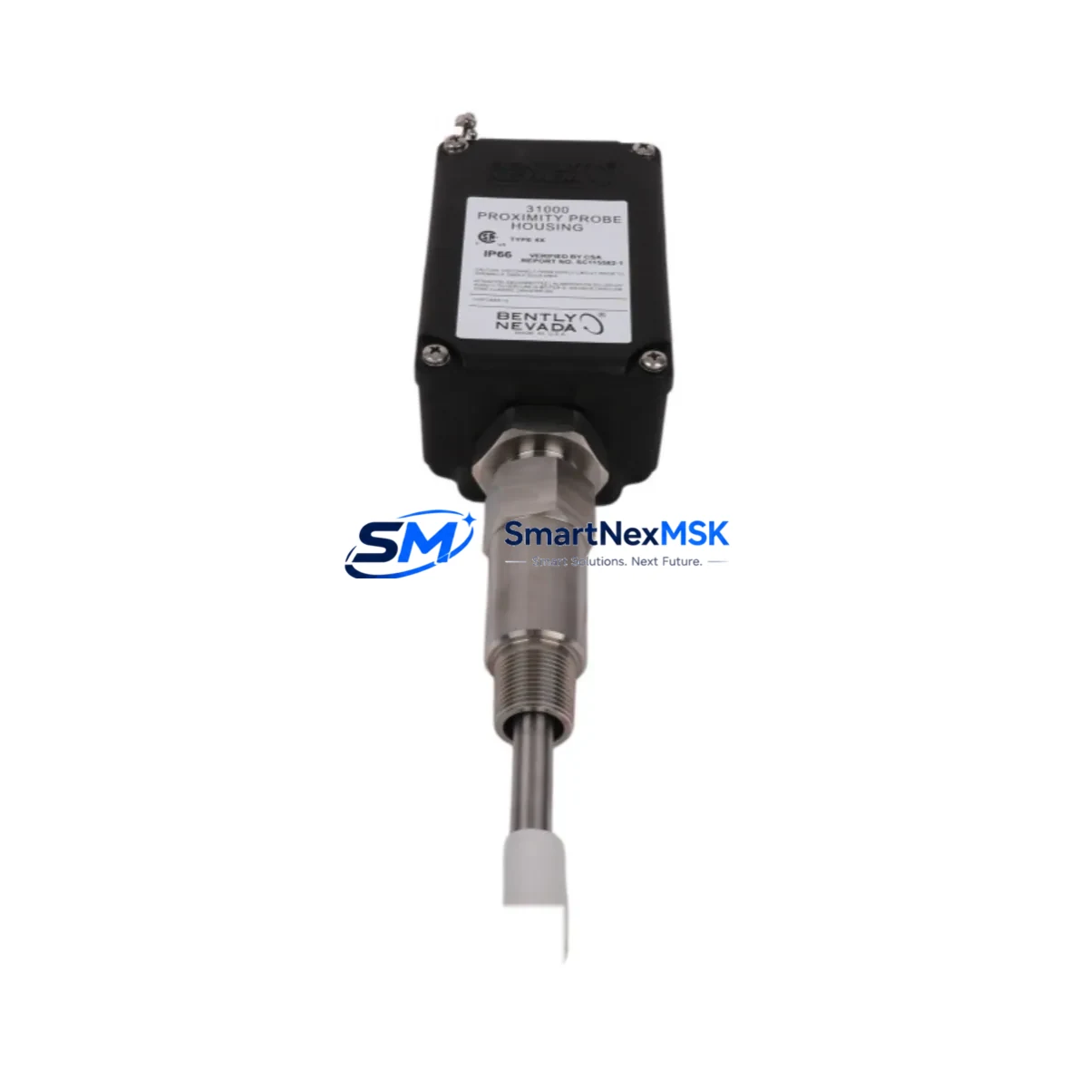
Bently Nevada 31000-28-05-00-061-01-02 Retrofit-Ready Proximity Probe Housing for 31000 Series Control Systems
The Bently Nevada 31000-28-05-00-061-01-02 is a precision-engineered proximity probe housing assembly designed for seamless integration into Bently Nevada 31000 Series continuous vibration monitoring systems. As legacy rotating machinery protection platforms approach end-of-life or face discontinued spare parts availability, this unit serves as a verified drop-in replacement that preserves existing wiring, mounting geometry, and signal chain integrity — enabling plant engineers to execute controlled retrofits without redesigning the monitoring architecture.
This housing assembly is engineered to interface directly with the Bently Nevada 3300 Series proximitor/seismic monitor and the 3500 Series machinery protection system rack, both of which remain widely deployed across turbomachinery, compressor trains, and pump stations in oil & gas, power generation, and petrochemical facilities. When paired with a compatible Bently Nevada 330100 or 330130 proximity probe and the corresponding 330180 extension cable, the 31000-28-05-00-061-01-02 housing maintains the required 200 mV/mil (7.87 V/mm) sensitivity standard, ensuring that existing vibration alarm and trip setpoints remain valid without recalibration of the 3500/40M or 3500/42M monitor modules.
For facilities operating older Bently Nevada 7200 Series or 9000 Series proximity systems, this housing assembly also supports migration pathways toward the 3500 platform. Engineers planning such upgrades should verify gap voltage settings at the proximitor output — typically –10 VDC at the nominal air gap — and confirm that the replacement housing thread specification (M10×1 or 3/8-24 UNF depending on variant) matches the existing probe port on the bearing housing or thrust collar bracket. Adapter sleeves and thread inserts are available where direct thread compatibility cannot be confirmed.
Upgrade Compatibility Table
| Parameter | 31000-28-05-00-061-01-02 | Notes / Retrofit Guidance |
|---|---|---|
| Series Compatibility | Bently Nevada 31000 Series | Also compatible with 3300 & 3500 Series signal chains |
| Probe Interface | 330100 / 330130 Proximity Probe | Verify tip diameter and gap range before installation |
| Extension Cable | 330180 Series | Total cable length must match proximitor calibration range |
| Proximitor Compatibility | 3300 XL 8mm, 3500/40M, 3500/42M | Confirm –24 VDC supply rail at proximitor terminal |
| Output Sensitivity | 200 mV/mil (7.87 V/mm) | No recalibration required for direct replacement |
| Thread Specification | M10×1 / 3/8-24 UNF (variant-dependent) | Confirm bearing housing port thread before ordering |
| Installation Clearance | Per OEM bearing housing drawing | Verify radial and axial clearance for probe tip |
| Communication Protocol | Analog (–24 VDC / 4–20 mA via monitor) | No protocol migration required for same-series swap |
| Rack Slot Requirement | N/A (field-mounted sensor) | Monitor module slot assignment unchanged |
| Warranty | 12 Months | Covers manufacturing defects; includes pre-shipment functional test |
Retrofit Planning for Existing Automation Systems
Successful integration of the 31000-28-05-00-061-01-02 into an existing machinery protection architecture requires a structured pre-installation review. Begin by auditing the current probe-to-proximitor cable run: the Bently Nevada 330180 extension cable must be terminated correctly at both the probe connector and the proximitor input terminal, with total system length kept within the calibrated range specified on the proximitor label. Incorrect cable length is one of the most common causes of gap voltage drift after a housing swap.
Next, inspect the 3500 Series rack for available I/O capacity. If the retrofit is part of a broader system expansion — for example, adding shaft radial vibration monitoring to a previously unmonitored bearing position — you may need to install an additional 3500/40M or 3500/42M monitor module and configure a new channel in the System 1 Evolution software or the legacy System 1 Classic platform. Ensure that the 3500 rack’s power supply module (such as the 3500/15 or 3500/05) has sufficient current headroom to support the additional proximitor load.
For plants running a Bently Nevada 1900/65A general-purpose equipment monitor or a 2300 Series online machinery monitor alongside the 31000 Series proximity system, confirm that the analog output signals from the new housing assembly are correctly mapped to the DCS historian or the plant’s safety instrumented system (SIS). In Yokogawa CENTUM VP or Honeywell Experion PKS environments, this typically involves updating the I/O assignment in the field control station (FCS) and verifying the engineering unit scaling in the HMI faceplate. Operators should also update any vibration trend displays in the SCADA or DCS graphics to reflect the new channel tag if the probe position label has changed.
Where the retrofit involves replacing a Bently Nevada 7200 Series housing with the 31000-28-05-00-061-01-02, pay particular attention to the proximitor supply voltage: the 7200 Series operates on –18 VDC, while the 3300/3500 platform requires –24 VDC. A power supply upgrade or a dedicated –24 VDC rail from the 3500/15 power supply module will be necessary. Document all wiring changes in the as-built drawings and update the loop diagrams before returning the machine to service.
Downtime Control During System Migration
Minimizing unplanned downtime during a proximity probe housing replacement is achievable through disciplined pre-staging and a clear bypass protocol. Before the maintenance window opens, pre-configure the replacement 31000-28-05-00-061-01-02 housing with the correct gap setting using a bench-top proximitor and a calibrated target disk. Record the gap voltage (target: –10 VDC ±0.5 VDC at nominal air gap) and attach the calibration record to the work order.
During the outage, place the affected 3500/40M or 3500/42M monitor channel in bypass mode via the front-panel keyswitch or through System 1 software to prevent spurious trips while the probe is disconnected. Retain the original program logic, alarm setpoints, and trip multipliers in the monitor module — these do not need to be modified for a same-series housing swap. After reinstalling the new housing and reconnecting the 330180 extension cable, verify the gap voltage at the proximitor output terminal before releasing the bypass. A gap voltage outside the –7 to –18 VDC acceptance window indicates a thread engagement or air gap error that must be corrected before the machine is restarted.
For facilities with redundant proximity probe pairs (X–Y configuration), it is best practice to replace one probe housing at a time, confirming correct operation of the first channel before proceeding to the second. This approach maintains at least one active vibration channel throughout the maintenance window, preserving the machine’s trip protection capability and satisfying most SIS proof-test requirements without a full machine shutdown.
Retrofit Support FAQ
Q1: Is the 31000-28-05-00-061-01-02 a direct drop-in replacement for the original Bently Nevada part?
Yes. This housing assembly is manufactured to the original dimensional and electrical specification. Thread form, probe tip recess depth, and connector pinout are identical to the factory part, allowing direct substitution without modification to the bearing housing port or the extension cable termination.
Q2: What pre-shipment testing is performed on each unit?
Every 31000-28-05-00-061-01-02 housing undergoes a functional gap voltage test using a calibrated 3300 XL proximitor and a reference target before shipment. The test record, including measured gap voltage and sensitivity confirmation, is included with each unit. All units are covered by a 12-month warranty against manufacturing defects from the date of shipment.
Q3: Can this housing be used with a Bently Nevada 3500/42M Thrust Position Monitor?
Yes, provided the probe is installed in a thrust collar application and the total probe-plus-cable system length matches the proximitor’s calibration range. Confirm the thrust position channel’s engineering unit scaling (typically expressed in mils or mm) in the 3500 rack configuration software before commissioning.
Q4: What documentation should I prepare before starting the retrofit?
Gather the existing loop diagram, the bearing housing drawing showing the probe port thread and clearance dimensions, the 3500 rack configuration printout, and the current System 1 channel configuration export. Having these documents on hand allows the field technician to verify wiring, confirm gap settings, and restore the monitor channel from bypass without delay, keeping total downtime to a minimum.
© 2026 SMARTNEXMSK. All rights reserved.
Original Source: https://smartnexmsk.com
Contact: [email protected] | +86 18259474341



