
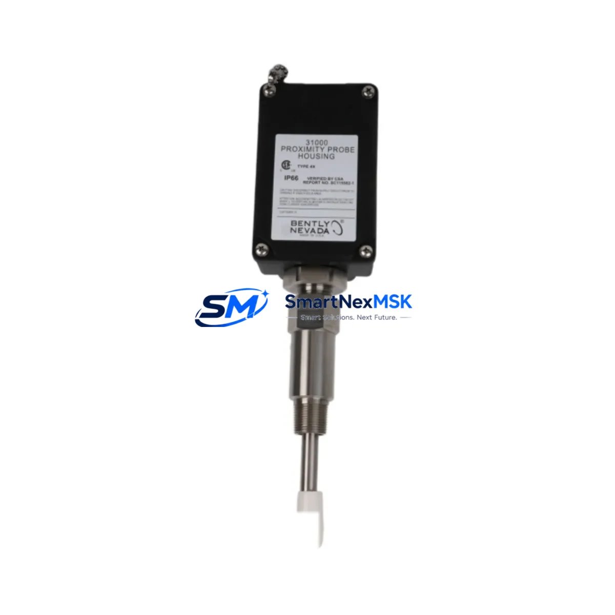
Bently Nevada 31000-31-05-20-080-00-02 Maintenance-Ready Spare for 31000 Series Automation
The Bently Nevada 31000-31-05-20-080-00-02 is an original proximity probe housing assembly engineered for continuous-duty vibration monitoring in rotating machinery protection systems. Designed as a direct maintenance spare within the Bently Nevada 3500 and 31000 Series ecosystem, this component supports rapid field replacement to minimize unplanned downtime in turbines, compressors, pumps, and critical rotating equipment. Each unit is sourced from verified supply channels, pre-shipment tested, and backed by a 12-month warranty — giving maintenance engineers and procurement teams the confidence to stock this part as a first-line spare.
For industrial facilities operating legacy Bently Nevada vibration monitoring systems, the 31000-31-05-20-080-00-02 represents a critical link in the machinery protection chain. Its housing assembly maintains precise probe-to-target gap geometry, which is essential for accurate eddy-current displacement measurement. Degraded or damaged housings introduce measurement drift, false alarms, and — in worst-case scenarios — missed trip events. Stocking this spare eliminates the risk of extended lead times during emergency shutdowns.
Spare Maintenance Table
| Parameter | Specification / Detail |
|---|---|
| Part Number | 31000-31-05-20-080-00-02 |
| Brand | Bently Nevada |
| Series | 31000 Series |
| Product Type | Proximity Probe Housing Assembly |
| Application | Eddy-current displacement / vibration monitoring |
| Compatible Systems | Bently Nevada 3500 Series, 31000 Series monitoring racks |
| Installation Environment | Industrial — turbines, compressors, pumps, gearboxes |
| Operating Temperature | -40°C to +120°C (typical for 31000 Series field hardware) |
| Origin | USA |
| Condition | Original / New — pre-shipment tested |
| Warranty | 12 Months |
| Lead Time | In stock — ships within 1-3 business days |
| Maintenance Recommendation | Replace housing when probe gap cannot be re-zeroed or physical damage is observed |
Maintenance Planning for Continuous Operation
When replacing the 31000-31-05-20-080-00-02 housing assembly during a planned or emergency maintenance event, a thorough inspection of the surrounding measurement loop is essential to restore full system integrity. Maintenance engineers should treat this replacement as an opportunity to audit the complete vibration channel.
Begin by inspecting the Bently Nevada 330130 proximity probe paired with this housing — probe tip wear or contamination is a common co-failure mode. Verify the 330180 extension cable for continuity and insulation integrity, as cable damage frequently accompanies housing failures in high-vibration environments. The 330500 proximitor / oscillator-demodulator should be bench-tested to confirm output voltage linearity before reinstalling the new housing assembly.
At the rack level, inspect the 3500/42M Proximitor / Seismic Monitor input card for any sign of channel fault LEDs or configuration drift. If the system uses a 3500/20 Rack Interface Module, confirm that the Modbus or RS-232 communication link to the DCS or SCADA is re-established after the replacement. For facilities running System 1 Evolution condition monitoring software, re-validate the channel calibration and gap voltage setpoints post-installation.
Procurement engineers building a comprehensive spare parts kit for 31000 Series installations should also consider stocking 3500/15 Power Supply modules — power interruptions during probe replacement can stress aging PSU capacitors. 3500/22M Transient Data Interface cards are another high-value spare for sites with transient capture requirements. Additionally, terminal block assemblies and I/O barrier modules within the 3500 rack should be inspected for corrosion or loose terminations whenever the probe circuit is broken for maintenance.
For installations in hazardous areas, confirm that the Zener barrier or galvanic isolator associated with this probe channel meets current IS certification requirements. Signal integrity from the proximitor to the monitor card depends on proper barrier impedance matching — a degraded barrier can mimic a failing probe housing and lead to misdiagnosis.
Site Replacement Workflow
Step 1 — Isolation and Permit: Obtain a work permit and isolate the affected machinery channel at the 3500 rack. Place the monitor in bypass mode to prevent spurious trips during the replacement procedure.
Step 2 — Gap Measurement and Documentation: Record the existing probe gap voltage (typically -10 VDC at nominal gap) before disassembly. This baseline is required for post-installation verification.
Step 3 — Housing Removal: Disconnect the extension cable from the probe. Unthread the 31000-31-05-20-080-00-02 housing from the mounting bracket. Inspect the bracket and target area for wear, scoring, or contamination.
Step 4 — New Housing Installation: Thread the replacement housing to the specified torque. Reinstall the 330130 probe and set the gap to the manufacturer’s nominal specification using a non-ferrous feeler gauge or gap voltage measurement.
Step 5 — Cable Reconnection and Loop Check: Reconnect the 330180 extension cable. Verify gap voltage at the proximitor output. Confirm the 3500 monitor card reads within the OK band before removing bypass.
Step 6 — System Restoration: Remove bypass, confirm alarm and trip setpoints are active, and log the replacement in the CMMS. Update spare parts inventory to trigger reorder of the consumed 31000-31-05-20-080-00-02 unit.
This workflow is compatible with legacy 31000 Series installations and current 3500 Series racks, ensuring backward compatibility and reducing the risk of configuration errors during the transition from older to newer monitoring hardware.
Spare Parts Support FAQ
Q1: Is the 31000-31-05-20-080-00-02 compatible with both the 3500 Series and older 31000 Series racks?
Yes. The housing assembly is designed for the 31000 Series probe interface and is mechanically and electrically compatible with Bently Nevada 3500 Series monitoring systems that use the same probe thread standard. Always verify the probe model and gap specification against your system documentation before installation.
Q2: What is included in the 12-month warranty and how does it apply to field-installed spares?
Each unit is pre-shipment tested and covered by a 12-month warranty from the date of delivery. The warranty covers manufacturing defects and functional failures under normal operating conditions. It does not cover damage resulting from improper installation, over-torquing, or exposure to conditions outside the rated operating envelope.
Q3: How should this part be stored as a long-term inventory spare?
Store in its original packaging in a dry, temperature-controlled environment (10°C-35°C, less than 70% RH). Avoid storage near strong magnetic fields or corrosive atmospheres. Inspect the probe thread and housing body annually for corrosion or mechanical damage. Rotate stock on a FIFO basis to maintain spare readiness.
Q4: Can this housing be replaced on a running system without a full shutdown?
Probe housing replacement on a live machine requires placing the affected monitor channel in bypass mode at the 3500 rack to prevent spurious trips. A full machine shutdown is strongly recommended for safe access to the probe mounting location. Consult your site safety procedures and the Bently Nevada installation manual before performing any work on a running machine.
© 2026 SMARTNEXMSK. All rights reserved.
Original Source: https://smartnexmsk.com
Contact: [email protected] | +86 18259474341



