
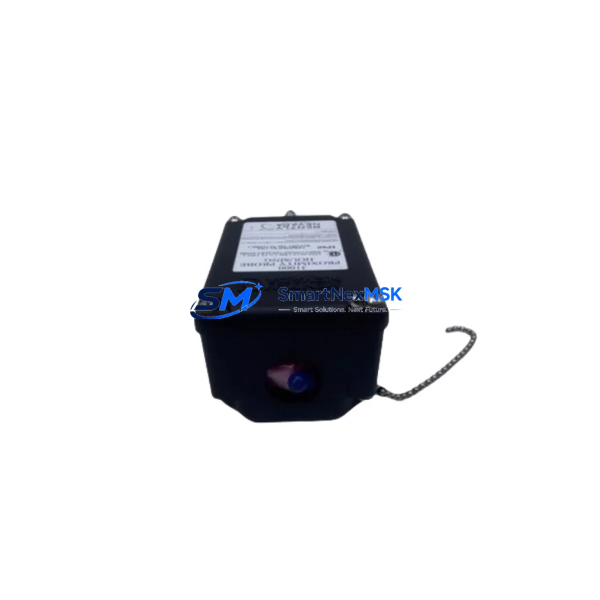
Bently Nevada 32000-16-05-08-070-03-02 Retrofit-Ready Proximity Probe for 3300 Series Control Systems
The Bently Nevada 32000-16-05-08-070-03-02 is a proximity probe housing assembly engineered for seamless integration into existing 3300 Series vibration monitoring and machinery protection systems. As legacy installations age and OEM support windows close, this unit serves as a verified drop-in replacement that preserves signal integrity, maintains gap voltage calibration, and eliminates the need for full-system requalification. Whether you are managing a planned outage, responding to an unplanned failure, or executing a phased control system upgrade, this probe delivers the dimensional and electrical compatibility required to restore continuous monitoring without reprogramming your Bently Nevada 3300 rack.
Sourced from authorized distribution channels and subject to pre-shipment functional verification, each unit is backed by a 12-month warranty covering manufacturing defects and electrical performance. Inventory is maintained in-stock to support urgent dispatch requirements, with global logistics options available for critical plant operations.
Upgrade Compatibility Table
| Parameter | 32000-16-05-08-070-03-02 (This Unit) | Notes / Retrofit Guidance |
|---|---|---|
| Series Compatibility | Bently Nevada 3300 Series | Direct replacement; no rack modification required |
| Probe Type | Proximity / Eddy Current | Confirm target material (steel/alloy) matches original spec |
| Cable Length | 5 ft (standard extension cable) | Pair with 330130 extension cable if field routing requires |
| Connector Interface | Standard BNC / coaxial | Verify mating connector on 3300/16 monitor module |
| Gap Voltage Range | −10 VDC nominal at 50 mil gap | Re-gap after installation; use gap voltage meter |
| Installation Requirement | Threaded housing, 8mm probe tip | Check bracket and probe holder dimensions before swap |
| Communication Compatibility | Analog signal to 3300 Series monitor | No protocol change; signal chain remains unchanged |
| Replacement Recommendation | Direct swap for failed or end-of-life probe | Replace extension cable and proximitor simultaneously if aged |
| Commissioning Focus | Gap setting, signal verification, alarm setpoint check | Confirm OK LED on 3300/16 monitor after installation |
| Warranty | 12 Months | Covers manufacturing defects and electrical performance |
Retrofit Planning for Existing Automation Systems
Integrating the 32000-16-05-08-070-03-02 into an aging machinery protection architecture requires a structured approach that accounts for the full signal chain, not just the probe itself. In a typical 3300 Series installation, the probe works in conjunction with a 330130-045-00-00 extension cable and a 3300/16 sixteen-channel monitor housed within a 3300 rack. Before pulling the failed probe, engineers should document the existing gap voltage reading, note the proximitor output voltage, and photograph the terminal wiring on the monitor module to preserve reference data for post-installation verification.
Power supply integrity is a frequently overlooked factor in retrofit projects. The 3300 rack relies on a dedicated −24 VDC power supply module, and any degradation in supply voltage will directly affect probe sensitivity and alarm thresholds. It is advisable to test the power supply output before and after the probe swap to rule out a secondary fault masking as a probe failure. If the rack is also running 3300/20 temperature monitors or 3300/46 tachometer input modules alongside the proximity channels, confirm that the total current draw remains within the rack’s rated capacity after any module additions.
For plants executing a broader migration from legacy 3300 architecture toward the System 1 platform or a newer rack-based solution, the 32000-16-05-08-070-03-02 provides a cost-effective bridge that keeps existing machinery protection active during the transition. This is particularly valuable in applications where the 3500 Series rack is being phased in incrementally, as it allows individual measurement points to be upgraded without forcing a full cutover. During this period, maintaining a parallel signal path and verifying that the DCS historian continues to receive valid vibration data from both old and new channels is essential for audit continuity.
HMI screens tied to the 3300 system should be reviewed to confirm that tag names, engineering unit scaling, and alarm limit displays remain accurate after the probe replacement. In facilities using a GE iFIX, Wonderware, or Rockwell FactoryTalk SCADA layer, the analog input card receiving the 4–20 mA converted signal from the proximitor should be checked for correct range configuration. If the plant uses a Modbus or PROFIBUS gateway to bridge the 3300 monitor outputs to the DCS, verify that the gateway polling cycle and register mapping are undisturbed after the physical swap.
Downtime Control During System Migration
Minimizing unplanned downtime during a proximity probe replacement begins with pre-staging all replacement components before the maintenance window opens. For the 32000-16-05-08-070-03-02, this means having the replacement probe, a calibrated gap voltage meter, the correct probe holder wrench, and a copy of the original installation drawing available at the work site before the machine is taken offline.
Where process conditions allow, a hot-swap approach can be used: the new probe is threaded into the spare probe port while the machine is still running, gap voltage is set to the nominal value, and the monitor channel is switched to the new probe input before the old probe is removed. This technique, supported by the 3300/16 monitor’s channel-by-channel enable/disable function, can reduce the monitoring gap to under two minutes in experienced hands.
For facilities where a cold swap is required, the priority is to restore the OK relay output on the 3300 monitor as quickly as possible, since many interlock and permissive logic circuits in the DCS or safety PLC depend on this signal. After physical installation, the commissioning sequence should follow: set gap voltage → verify OK LED → check vibration reading against a known baseline → confirm alarm and danger setpoints → release the channel to normal monitoring. Keeping a pre-written commissioning checklist specific to the 3300 Series reduces the risk of missed steps under time pressure and supports the post-maintenance documentation required by most plant safety management systems.
Original program logic in the safety PLC or DCS controller does not require modification when replacing a like-for-like probe, provided the signal scaling and tag assignments remain unchanged. This is one of the key advantages of sourcing a direct replacement rather than an alternative-brand substitute that may require recalibration of the entire measurement chain.
Retrofit Support FAQ
Q: Is the 32000-16-05-08-070-03-02 a direct replacement for my existing 3300 Series probe without any wiring changes?
A: Yes, provided the replacement unit shares the same cable length, connector type, and probe tip diameter as the original. Verify the extension cable part number and proximitor model before installation. In most standard 3300 Series configurations, no terminal rewiring is required.
Q: What commissioning steps are required after installing this probe?
A: Set the probe gap to achieve the nominal −10 VDC output at the proximitor, verify the OK LED on the 3300/16 monitor, confirm the vibration reading is within expected baseline range, and check that all alarm and danger setpoints are active. Document the as-found and as-left gap voltage readings for maintenance records.
Q: Has this unit been tested before shipment?
A: Yes. Each 32000-16-05-08-070-03-02 unit undergoes pre-shipment electrical verification including output voltage check and continuity test. Units are shipped with a test report and are covered by a 12-month warranty from the date of delivery.
Q: Can this probe be used in a system being migrated from 3300 Series to 3500 Series architecture?
A: Yes. During a phased migration, this probe can continue to serve the legacy 3300 rack while new 3500 Series monitor modules are installed on other measurement points. This allows a controlled, channel-by-channel transition without forcing a full system cutover, reducing both risk and downtime exposure.
© 2026 SMARTNEXMSK. All rights reserved.
Original Source: https://smartnexmsk.com
Contact: [email protected] | +86 18259474341



