
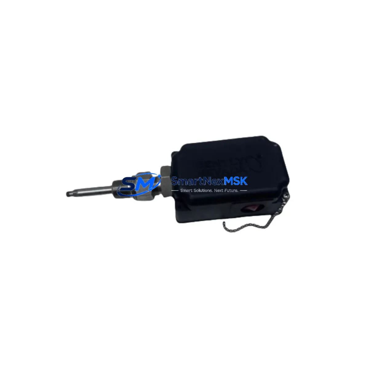
Bently Nevada 32000-28-05-05-110-03-02 Spare 3300 Automation: Spare Replacement & Industrial Downtime Risk Control
The Bently Nevada 32000-28-05-05-110-03-02 is an original proximity probe housing assembly engineered for the 3300 Series continuous vibration monitoring system. Designed for critical rotating machinery protection in power generation, petrochemical, oil & gas, and heavy industrial environments, this component plays a central role in shaft displacement measurement, radial vibration sensing, and machinery health monitoring. When this housing assembly fails or degrades, the entire vibration monitoring loop is compromised — creating unacceptable risk for turbines, compressors, pumps, and other rotating assets.
At SMARTNEXMSK, we stock original Bently Nevada spare parts with full traceability, pre-shipment electrical testing, and a 12-month warranty. Our inventory is maintained specifically to support maintenance engineers and procurement teams who need fast, reliable access to genuine replacement components — without the lead times of OEM channels.
Spare Maintenance Table
| Parameter | Specification / Detail |
|---|---|
| Part Number | 32000-28-05-05-110-03-02 |
| Brand | Bently Nevada |
| Series | 3300 Series Vibration Monitoring System |
| Product Type | Proximity Probe Housing Assembly |
| Sensing Technology | Eddy-current non-contact displacement |
| Probe Thread Size | 8 mm (standard 3300 Series) |
| Cable Length Compatibility | Compatible with 3300 XL 8mm extension cable assemblies |
| Target Material | Steel / Stainless Steel rotating shaft |
| Operating Temperature | -35°C to +120°C (probe tip) |
| Installation Environment | Industrial: turbines, compressors, pumps, gearboxes |
| Compatibility | Bently Nevada 3300 Series monitors, 3500 Series (with adapter), TK3 drivers |
| Origin | United States |
| Condition | Original, new or reconditioned-to-spec |
| Pre-shipment Testing | Electrical continuity, gap voltage, sensitivity verification |
| Warranty | 12 Months from date of shipment |
| Lead Time | In stock — ships within 2 business days |
Maintenance Planning for Continuous Operation
For maintenance engineers managing rotating machinery protection systems, replacing the 32000-28-05-05-110-03-02 housing assembly is rarely an isolated task. A thorough site inspection and planned replacement should also address the surrounding measurement chain and control cabinet components to prevent repeat failures and ensure system integrity.
Begin by inspecting the 3300 XL 8mm extension cable (typically part of the 330130 series) for jacket cracking, connector corrosion, or impedance drift — cable degradation is a leading cause of false vibration alarms and should be replaced simultaneously with the probe housing. The 3300 XL proximitor sensor (driver module, e.g., 330180 series) should be bench-tested for output voltage linearity; a worn driver will misread even a new probe assembly.
Inside the control cabinet, verify the Bently Nevada 3500/42M Proximitor I/O module for channel alarm setpoints and confirm that the 3500 rack power supply (e.g., 3500/15 or 3500/05) is delivering stable ±24 VDC to all monitor cards. Voltage sag under load is a common but overlooked cause of intermittent vibration channel faults. Check the terminal block wiring at the I/O module for loose ferrules and verify shield grounding continuity — ungrounded cable shields introduce noise that corrupts displacement readings.
For systems with communication integration, inspect the 3500/92 communication gateway module or Modbus/TCP interface card to confirm that vibration data is being correctly transmitted to the DCS or SCADA historian. A probe housing replacement that is not followed by a channel re-calibration and communication verification can result in silent data loss at the control room level.
Where the 3300 Series feeds into a broader machinery protection philosophy, also review the 3500/40M velocity monitor for bearing housing vibration and the 3500/46M position monitor for axial thrust — these channels share the same rack infrastructure and are often affected by the same power or grounding issues that degrade proximity probe performance. Finally, confirm that the keyphasor module (e.g., 3500/25) is providing a clean once-per-revolution reference signal, as phase-referenced vibration analysis depends entirely on keyphasor signal quality.
Maintaining a minimum spare inventory of one complete probe-cable-driver assembly per critical machine train is strongly recommended. For plants with more than four monitored machines, a spare 3500 I/O module and a spare rack power supply should be held on-site to support emergency recovery within a single shift.
Site Replacement Workflow
Step 1 — Isolation & Permit: Obtain a work permit and isolate the affected measurement channel at the 3500 rack. Do not de-energize the full rack unless required — most 3500 systems support hot-swap of I/O modules, but probe replacement at the machine requires a local isolation procedure.
Step 2 — Gap Measurement & Documentation: Before removing the old housing assembly, record the existing probe gap voltage (typically –10 VDC ±0.2 V at nominal gap). This baseline is required for post-installation verification. Photograph the cable routing and connector orientation.
Step 3 — Housing Removal: Unthread the 32000-28-05-05-110-03-02 housing from the probe bracket using the correct spanner. Inspect the bracket threads and mounting surface for corrosion or mechanical damage. Clean and re-tap threads if necessary before installing the replacement.
Step 4 — New Assembly Installation: Install the replacement housing assembly and torque to the manufacturer specification. Reconnect the extension cable, ensuring the connector is fully seated and the locking ring is engaged. Verify cable routing avoids heat sources and mechanical contact points.
Step 5 — Gap Setting & Calibration: Adjust the probe gap to achieve the nominal output voltage specified for the target material and probe model. Use a calibrated gap tool or feeler gauge. Confirm the proximitor output is within the linear range (typically –2 VDC to –18 VDC).
Step 6 — Channel Verification: At the 3500 rack, confirm the channel is reading correctly, alarm setpoints are active, and no fault indicators are present. Log the as-left gap voltage and sign off the work order. Notify the control room to confirm vibration data is restored in the historian.
This workflow minimizes downtime, preserves system compatibility, and ensures the replacement is fully commissioned before the machine is returned to service.
Spare Parts Support FAQ
Q1: Is the 32000-28-05-05-110-03-02 compatible with both the 3300 and 3500 Series monitoring systems?
The 32000-28-05-05-110-03-02 housing assembly is a native 3300 Series component. It is mechanically and electrically compatible with 3300 XL 8mm probe systems. Integration with 3500 Series racks is possible when used with the appropriate 3300 XL proximitor driver and correctly configured I/O module channel. Always verify the driver model and rack configuration before installation in a 3500 environment.
Q2: What pre-shipment testing is performed on this spare part?
Every unit shipped by SMARTNEXMSK undergoes electrical continuity verification, connector integrity inspection, and where applicable, gap voltage and sensitivity testing against Bently Nevada factory specifications. A test record is available upon request. Units that do not meet specification are not shipped.
Q3: How should this part be stored if it is held as a long-term spare?
Store in the original packaging or an anti-static, moisture-resistant enclosure. Recommended storage conditions: 15°C to 35°C, relative humidity below 70%, away from direct sunlight and electromagnetic sources. Inspect connector contacts and cable jacket annually. For storage exceeding 24 months, perform a bench test before installation.
Q4: What does the 12-month warranty cover?
The 12-month warranty covers manufacturing defects, electrical failure under normal operating conditions, and specification non-conformance identified after installation. It does not cover damage resulting from incorrect installation, overvoltage, mechanical impact, or use outside the specified environmental range. Warranty claims are processed within 5 business days of receiving the returned unit with a completed fault report.
© 2026 SMARTNEXMSK. All rights reserved.
Original Source: https://smartnexmsk.com
Contact: [email protected] | +86 18259474341



