
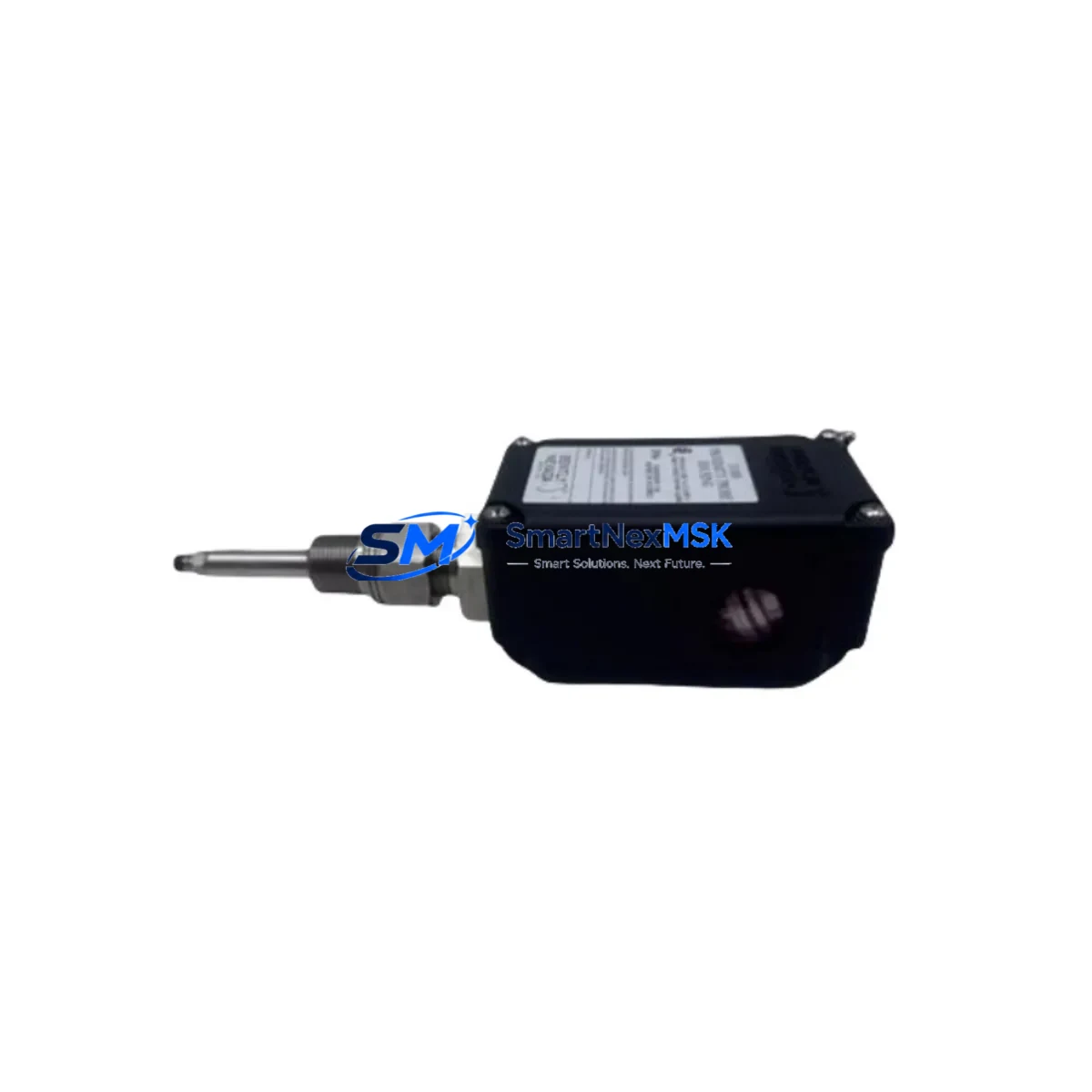
Bently Nevada 32000-29-05-10-075-07-02 Retrofit-Ready Proximity Probe Housing for 31000/32000 Control Systems
The Bently Nevada 32000-29-05-10-075-07-02 is a retrofit-ready proximity probe housing engineered for seamless integration into legacy 31000 and 32000 Series vibration monitoring and machinery protection systems. As original Bently Nevada 31000 Series components approach end-of-life and spare parts become increasingly scarce, this housing provides a verified drop-in replacement path that preserves existing wiring, signal conditioning infrastructure, and Keyphasor reference inputs without requiring a full system overhaul.
Designed for industrial environments where uptime is non-negotiable, the 32000-29-05-10-075-07-02 maintains full dimensional and electrical compatibility with the 3300 XL 8mm proximity transducer system and the broader Bently Nevada 3500 Series rack-based monitoring platform. Engineers undertaking control cabinet upgrades, rotating machinery protection retrofits, or predictive maintenance infrastructure modernization will find this housing a reliable anchor point for their migration strategy.
Upgrade Compatibility Table
| Parameter | Details |
|---|---|
| SKU / Part Number | 32000-29-05-10-075-07-02 |
| Brand | Bently Nevada |
| Compatible Series | 31000 Series, 32000 Series, 3300 XL, 3500 Series |
| Replaces / Supersedes | 31000-xx-xx proximity probe housings (direct retrofit) |
| Probe Gap / Extension Cable | Compatible with 330130, 330180 extension cables |
| Mounting Interface | Standard 3/8-24 UNF thread; no bracket modification required |
| Signal Compatibility | -24 VDC bias voltage; eddy-current output signal retained |
| Communication Protocol | Analog 4–20 mA / voltage output; compatible with 3500/40M and 3500/42M monitor modules |
| Installation Requirement | Verify probe gap (typically 1.0–2.0 mm) after installation using oscilloscope or gap meter |
| Commissioning Note | Re-confirm Keyphasor phase reference and OK relay setpoints in 3500 rack after swap |
| Warranty | 12 Months — covers manufacturing defects and signal output performance |
Retrofit Planning for Existing Automation Systems
Successful integration of the 32000-29-05-10-075-07-02 into an existing machinery protection architecture begins with a thorough audit of the current installation. Before removing the legacy 31000 Series housing, technicians should document the existing probe gap voltage (typically between -10 V and -18 V DC at operating clearance), verify the routing and condition of the 330180 or 330130 armored extension cable, and confirm that the driver/oscillator module — commonly a 3300 RAM or 3300 XL proximitor — is functioning within specification.
In systems built around the Bently Nevada 3500 Series rack, the 3500/20 rack interface module and 3500/40M proximitor monitor should be checked for firmware revision compatibility before the new housing is installed. If the existing rack includes a 3500/32 4-channel relay module for alarm and trip outputs, setpoint values should be exported from System 1 software or the 3500 Rack Configuration Utility prior to any hardware swap to prevent loss of protection logic.
For plants running older DCS platforms — such as Honeywell TDC 3000, ABB Advant, or Foxboro I/A Series — the analog 4–20 mA output from the proximity monitoring chain feeds directly into field termination assemblies (FTAs) and process interface units (PIUs). These signal paths remain fully intact when replacing the probe housing, as the electrical interface is preserved at the proximitor output stage. No re-engineering of the DCS I/O card assignments or controller tag databases is required.
Where the plant uses a Bently Nevada 1900/65A general-purpose vibration monitor or a standalone 3300 Series proximitor in a simplex configuration, the retrofit procedure is equally straightforward: remove the legacy housing, install the 32000-29-05-10-075-07-02, re-establish the probe gap, and verify the OK LED status on the proximitor front panel. If the system includes a 3500/22M transient data interface for waveform capture, confirm that the dynamic signal path is re-established and that the System 1 software is receiving valid waveform data before returning the machine to service.
Plants upgrading from older 7200 Series proximity systems to the 32000 platform should also review the junction box wiring and ensure that the coaxial cable impedance (typically 50 Ω) is maintained throughout the extension cable run. Mixing cable types or using non-Bently Nevada extension cables can introduce signal attenuation that affects gap voltage accuracy and vibration amplitude readings.
Downtime Control During System Migration
Minimizing unplanned downtime during a proximity probe housing replacement requires a structured pre-outage preparation protocol. Before the maintenance window opens, the replacement 32000-29-05-10-075-07-02 unit should be bench-tested using a calibrated gap simulator to confirm output linearity across the full measurement range. This pre-shipment verification — which is included as part of our standard 12-month warranty process — ensures that the unit arrives ready for immediate installation without requiring on-site calibration from scratch.
During the swap, the original program logic in the associated PLC or DCS controller does not require modification, as the proximity probe housing replacement is transparent to the control layer. Alarm and trip setpoints stored in the 3500 rack or the System 1 database remain valid, provided the new housing is installed at the same probe gap as the original. If the machine has been in service for an extended period and the shaft surface condition has changed, a minor gap adjustment may be necessary — this should be performed with the machine at rest and confirmed with a digital voltmeter before restart.
To further protect control continuity, it is recommended to place the affected 3500 rack channel in bypass mode (using the 3500/20 rack interface or System 1 software) during the physical swap. This prevents spurious trip signals from propagating to the 3500/32 relay module and triggering an unintended machine shutdown. Once the new housing is installed and the gap voltage is confirmed within the OK band, the bypass can be removed and the channel returned to normal protection status.
For facilities with redundant monitoring configurations — such as dual-probe XY arrangements feeding a 3500/40M dual-channel monitor — only one channel needs to be bypassed at a time, allowing the redundant channel to maintain full protection coverage throughout the replacement procedure. This approach effectively reduces the protection gap to zero and keeps the machine in a continuously monitored state during the entire retrofit operation.
Retrofit Support FAQ
Q1: Is the 32000-29-05-10-075-07-02 a direct drop-in replacement for 31000 Series proximity probe housings?
Yes. The 32000-29-05-10-075-07-02 is dimensionally and electrically compatible with the 31000 Series housing family. The 3/8-24 UNF thread form, body diameter, and electrical interface are retained, allowing direct installation without bracket modification or re-wiring of the extension cable or proximitor.
Q2: What commissioning steps are required after installation?
After physical installation, verify the probe gap voltage using a digital voltmeter at the proximitor output terminals. The OK band is typically -10 V to -18 V DC. Confirm the OK LED is illuminated on the proximitor or 3500 monitor module, then remove any bypass applied during the swap. If the system uses System 1 software, verify that the channel is returning valid static and dynamic data before signing off on the work order.
Q3: Will the replacement affect existing wiring or PLC/DCS program logic?
No. The proximity probe housing replacement is transparent to the control layer. Existing extension cable wiring, proximitor connections, and DCS or PLC tag assignments remain unchanged. No program modifications, I/O remapping, or HMI screen updates are required as a result of this hardware swap.
Q4: What does the 12-month warranty cover, and how is it validated?
The 12-month warranty covers manufacturing defects and confirmed signal output performance deviations from Bently Nevada specification. Each unit undergoes pre-shipment functional testing. Warranty claims are supported by our technical team with documented test records. Contact [email protected] with your order reference and a description of the observed fault to initiate a warranty review.
© 2026 SMARTNEXMSK. All rights reserved.
Original Source: https://smartnexmsk.com
Contact: [email protected] | +86 18259474341



