
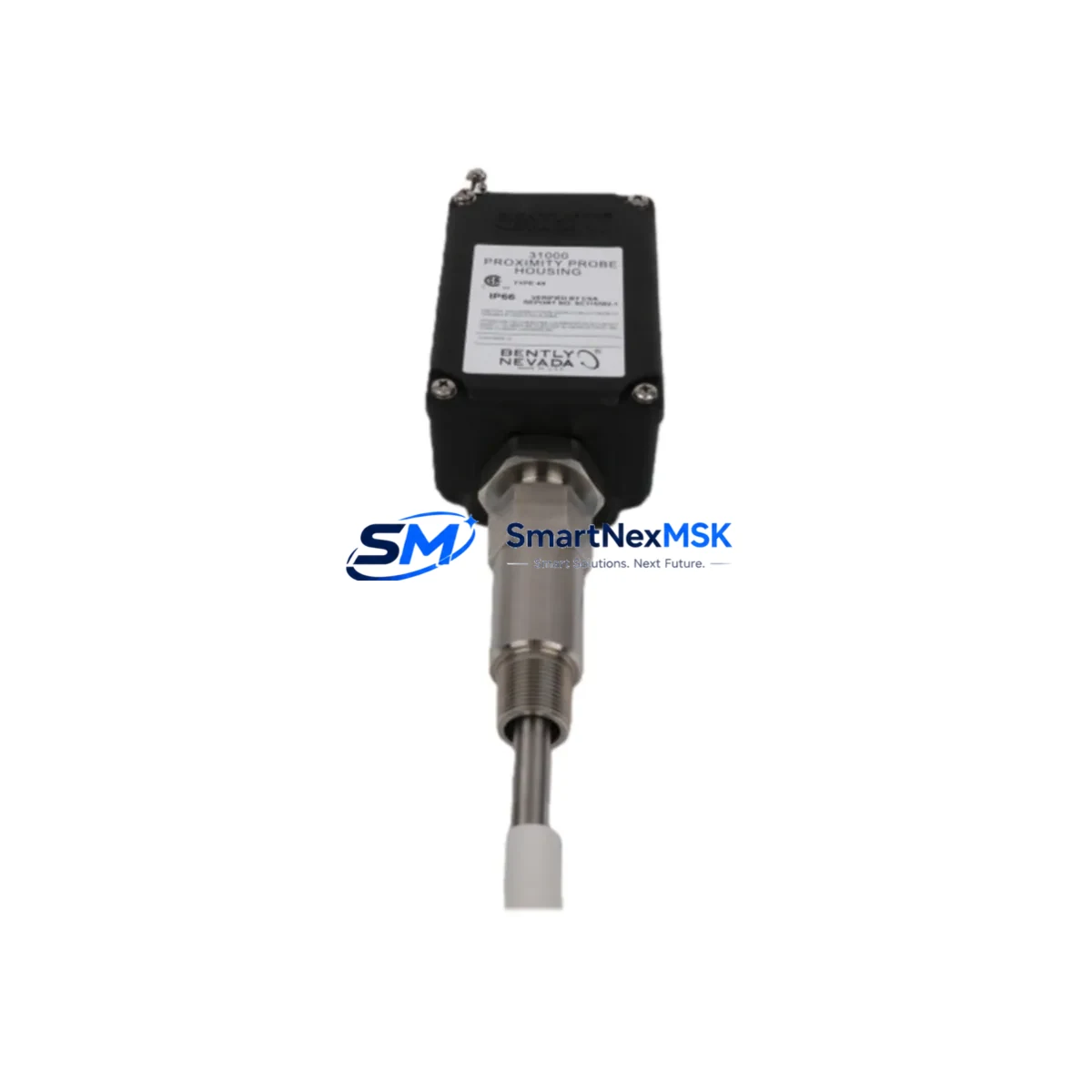
Bently Nevada 32000-29-10-04-055-03-02 Proximity Probe Housing: Retrofit-Ready Replacement for 32000 Series Control Systems
The Bently Nevada 32000-29-10-04-055-03-02 is a metric-series proximity probe housing engineered for the Bently Nevada 32000 Series vibration monitoring platform — one of the most widely deployed machinery protection systems in rotating equipment applications worldwide. As original equipment ages and OEM support windows close, this component serves as a verified drop-in replacement for facilities undertaking planned maintenance, emergency spares replenishment, or full-scale control system modernization.
Whether your plant is running a legacy 3300 Series rack alongside a newer System 1 monitoring architecture, or migrating from older 7200 Series transducer assemblies to current-generation 3500 Series monitoring modules, the 32000-29-10-04-055-03-02 housing maintains dimensional and electrical compatibility across the 32000 transducer family. Its metric thread specification and standardized cable connector interface allow direct installation without modification to existing conduit runs, junction boxes, or probe driver wiring.
Upgrade Compatibility Table
| Parameter | Details |
|---|---|
| SKU / Part Number | 32000-29-10-04-055-03-02 |
| Brand | Bently Nevada |
| Series Compatibility | Bently Nevada 32000 Series; cross-compatible with 3300 XL and 7200 Series probe assemblies (verify gap voltage) |
| Thread Specification | Metric (M8 × 1.0 standard); confirm with existing probe driver before installation |
| Mounting Interface | Direct replacement; no bracket modification required for standard 32000 Series installations |
| Communication Compatibility | Passive transducer housing — compatible with all Bently Nevada Proximitor® sensor drivers including 3300 XL 8mm, 3300 5mm, and 7200 Series drivers |
| Replacement Recommendation | Suitable for direct swap of worn, damaged, or discontinued 32000-series housings; re-gap and re-calibrate after installation |
| Commissioning Notes | Verify gap voltage (typically −10 VDC ±0.5 V at nominal gap); confirm OK/NOT OK relay setpoints in monitoring rack |
| Warranty | 12 Months from date of shipment |
| Origin | United States |
Retrofit Planning for Existing Automation Systems
Successful integration of the 32000-29-10-04-055-03-02 into an existing machinery protection loop requires a structured approach to hardware, wiring, and software compatibility. Before removing the legacy housing, engineers should document the current gap voltage reading, probe-to-target distance, and the Proximitor® sensor driver model — typically a 3300 XL Proximitor® or a 7200 Series Proximitor® — to ensure the replacement housing maintains the same sensitivity factor (V/mm or V/mil) required by the monitoring rack.
On the rack side, plants running a Bently Nevada 3500 Series monitoring system should verify that the I/O module assigned to the affected channel — such as a 3500/42M Proximitor®/Seismic Monitor or a 3500/40M Proximitor® Monitor — is configured for the correct transducer type and gap range. If the existing rack uses a 3300 Series monitor, confirm that the channel’s full-scale range and alarm setpoints are documented before the housing swap, as re-gapping may shift the DC output voltage and trigger nuisance alarms during commissioning.
For plants that have already migrated their primary protection to a System 1 Evolution software platform, the probe replacement workflow should include a channel inhibit command issued from the System 1 operator console before physical work begins. This prevents spurious machine-trip events during the re-gapping procedure. Once the 32000-29-10-04-055-03-02 housing is installed and the gap is set, the channel inhibit should be released only after the gap voltage is confirmed stable and within the driver’s linear range.
Wiring continuity between the probe housing, the interconnect cable (typically an 330130 or 330180 Series extension cable), and the Proximitor® sensor driver must be verified with a continuity check before energizing the loop. Plants using armored cable assemblies in hazardous-area installations should inspect the cable gland and conduit seal integrity as part of the same work order. If the existing extension cable shows signs of insulation degradation, replacing it alongside the housing — using a compatible 330130-080-00-00 or equivalent extension cable — eliminates a common source of intermittent signal faults that can be misdiagnosed as monitor or rack faults.
For facilities managing a broader control cabinet upgrade — for example, transitioning from a legacy Allen-Bradley PLC-5 or SLC 500 safety interlock to a modern ControlLogix L8x platform — the proximity probe loop often feeds a hardwired trip relay or a safety-rated DI card. Confirm that the new DI module’s input voltage threshold is compatible with the Proximitor® driver’s OK relay output before finalizing the cabinet redesign. Similarly, if the plant’s DCS — such as a Honeywell Experion PKS or Emerson DeltaV — is receiving the vibration signal via a 4–20 mA transmitter card, verify that the transmitter’s span is reconfigured to match the new probe’s sensitivity after installation.
Downtime Control During System Migration
Minimizing unplanned downtime during a proximity probe housing replacement is primarily a matter of preparation. The most effective strategy is to pre-stage the 32000-29-10-04-055-03-02 replacement housing, along with any associated extension cables and Proximitor® sensor drivers, at the work site before the maintenance window opens. A pre-tested spare — one that has been bench-verified for gap voltage response and OK relay function — can reduce in-field commissioning time from hours to minutes.
Where the monitoring system permits, placing the affected channel in bypass mode (rather than a full rack inhibit) allows the remaining channels on the same 3500 Series or 3300 Series rack to continue protecting the machine during the swap. This is particularly important on critical rotating equipment such as compressors, turbines, or pumps where a full rack inhibit would remove all vibration protection simultaneously.
Original program logic in the safety PLC or DCS should be exported and archived before any field work begins. If the probe replacement is part of a larger I/O migration — for example, moving from a legacy Modbus RTU loop to a PROFIBUS DP or EtherNet/IP network — the control program should be tested in simulation mode against the new I/O map before the cutover. This protects the integrity of existing HMI faceplates, historian tags, and alarm configurations, and ensures that operators see consistent data immediately after the migration window closes.
All replacement components supplied by SMARTNEXMSK are pre-shipment tested and shipped with a 12-month warranty from the date of delivery. In-stock units are available for same-day dispatch, supporting emergency maintenance scenarios where machine availability is critical.
Retrofit Support FAQ
Q1: Is the 32000-29-10-04-055-03-02 a direct drop-in replacement for my existing 32000 Series probe housing?
In most standard 32000 Series installations, yes. The housing shares the same metric thread specification and connector interface as the original. However, after installation you must re-gap the probe to the target and verify the gap voltage is within the Proximitor® driver’s linear range before returning the channel to service. Always cross-reference the probe driver’s sensitivity specification (V/mm) with the replacement housing’s datasheet.
Q2: What commissioning steps are required after installing this replacement housing?
After mechanical installation, set the probe-to-target gap per the driver’s specification (typically 1.0–1.5 mm for 8 mm probes). Measure the DC gap voltage at the Proximitor® driver output and confirm it falls within the linear range (typically −10 VDC ±0.5 V at nominal gap). Check the OK relay status, release any channel inhibit or bypass, and confirm that the monitoring rack — whether a 3500 Series, 3300 Series, or equivalent — is displaying a valid vibration reading before signing off the work order.
Q3: Can this housing be used with both 3300 Series and 3500 Series Proximitor® drivers?
Yes, provided the driver’s sensitivity factor and gap range are compatible with the housing’s dimensional specification. The 32000 Series housing is designed for use with standard Bently Nevada Proximitor® drivers. Confirm the driver model and its published sensitivity (V/mm or V/mil) before installation, and re-calibrate the gap accordingly. If you are unsure of compatibility, contact our technical team with your driver model number for confirmation.
Q4: What warranty and testing does SMARTNEXMSK provide with this part?
All units are covered by a 12-month warranty from the date of shipment. Each unit undergoes pre-shipment functional testing to verify mechanical integrity and connector condition. In-stock units are available for immediate dispatch. For urgent requirements, contact our sales team directly to confirm lead time and arrange expedited shipping.
© 2026 SMARTNEXMSK. All rights reserved.
Original Source: https://smartnexmsk.com
Contact: [email protected] | +86 18259474341



