
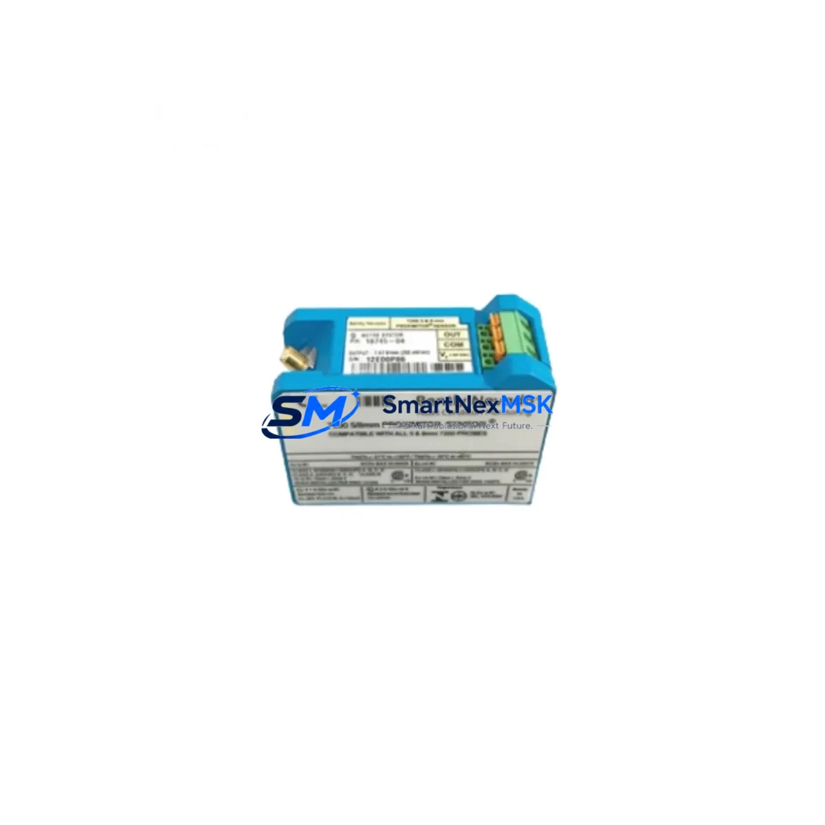
Bently Nevada 3300/12-01-20-01 Spare for 3300 Series Automation
The Bently Nevada 3300/12-01-20-01 is a dual-channel proximitor/seismic monitor module engineered for continuous machinery protection within the 3300 Series condition monitoring system. As rotating equipment — turbines, compressors, pumps, and gearboxes — forms the backbone of process-critical operations, the availability of a verified, maintenance-ready spare for this module is a non-negotiable element of any serious MRO strategy. Unplanned downtime caused by a failed vibration monitor can cascade into hours or days of lost production; having a tested, original-specification replacement on the shelf is the single most effective countermeasure.
This unit ships fully tested against factory electrical parameters, packaged for safe transit, and backed by a 12-month warranty. Each module is inspected for connector integrity, channel isolation, and signal output accuracy before dispatch, ensuring that field installation proceeds without diagnostic delays.
Spare Maintenance Table
| Parameter | Specification / Detail |
|---|---|
| Part Number | 3300/12-01-20-01 |
| Brand | Bently Nevada |
| Series | 3300 Series Machinery Protection System |
| Module Type | Dual-Channel Proximitor / Seismic Monitor |
| Measurement Channels | 2 (radial vibration / axial position / seismic) |
| Input Signal | Proximitor / velocity transducer (eddy-current compatible) |
| Output | 4–20 mA analog, relay contact outputs |
| Power Supply | 24 VDC (via 3300 Series rack backplane) |
| Rack Compatibility | Bently Nevada 3300 Series 4-slot / 6-slot rack |
| Operating Temperature | 0 °C to +60 °C |
| Mounting | DIN-rail rack card, front-panel extraction |
| Alarm Relay | Alert / Danger relay, configurable thresholds |
| Origin | USA (Original Bently Nevada manufacture) |
| Condition | Original spare — new or refurbished-to-spec |
| Pre-shipment Test | Full electrical and signal-path verification |
| Warranty | 12 Months |
| Lead Time | Ships within 1–3 business days |
Maintenance Planning for Continuous Operation
When a maintenance or reliability engineer schedules replacement of the 3300/12-01-20-01 monitor module, the scope of inspection should extend beyond the card itself. The 3300 Series rack is an integrated system, and a single-point failure often reveals adjacent wear or marginal components that will become the next unplanned outage.
Begin with the 3300/05 power supply module that feeds the rack backplane — verify output voltage stability under load, as a sagging supply rail can cause false trips or erratic alarm behavior that is misdiagnosed as a monitor card fault. Inspect the 3300/55 keyphasor module if shaft-speed reference signals are used for phase-referenced vibration analysis; a degraded keyphasor output corrupts vector data across all channels in the rack.
Check the 3300/16 I/O module or terminal board associated with the affected channels. Loose field wiring terminations at the I/O terminal strip are a leading cause of intermittent channel faults and should be re-torqued to specification during any card swap. Inspect the proximitor sensor cables (typically 3300 XL 8mm or 11mm probe assemblies) for jacket cracking, connector corrosion, and extension cable continuity — a degraded cable presents as a monitor card fault even when the card itself is healthy.
If the machine train includes seismic velocity transducers, verify the transducer mounting integrity and cable shielding continuity. Unshielded or poorly grounded signal cables introduce noise that exceeds the monitor’s input range, triggering nuisance alarms. Review the 3300/46 or 3300/50 relay output modules in the same rack to confirm that alarm relay contacts are not welded or corroded — relay failures are silent until a real alarm event occurs.
For systems integrated with a System 1 Evolution or legacy System 1 condition monitoring software platform, confirm that the replacement module’s configuration file matches the original channel assignments, full-scale ranges, and alarm setpoints before returning the machine to service. A misconfigured replacement card that passes bench tests can still cause a spurious trip in the field.
Finally, inspect the rack backplane connector pins for fretting corrosion, particularly in high-vibration environments. A 3300 Series rack chassis with damaged backplane connectors will cause recurring card failures regardless of how many replacement modules are installed. Addressing the root cause at the rack level is essential for long-term system reliability.
Site Replacement Workflow
Step 1 — Isolation: Coordinate with operations to place the affected machine train in a safe state. Inhibit the alarm relay outputs at the 3300/46 relay module or via the System 1 software to prevent a spurious trip during card extraction.
Step 2 — Documentation: Record the existing channel configuration, alarm setpoints, and full-scale range from the front-panel display or System 1 database before removing the card. Photograph the terminal board wiring if field modifications have been made.
Step 3 — Card Extraction: Release the front-panel locking lever and extract the 3300/12-01-20-01 module from the rack slot. Inspect the backplane connector on the extracted card and the rack chassis for pin damage or contamination.
Step 4 — Replacement Installation: Insert the replacement module, confirm the locking lever engages fully, and verify that the power LED illuminates. Restore field wiring connections at the I/O terminal board and re-torque to specification.
Step 5 — Configuration Verification: Apply the saved configuration file or manually re-enter channel parameters. Confirm that live vibration readings from the proximitor probes are within expected baseline ranges before releasing the alarm inhibit.
Step 6 — Return to Service: Remove the alarm inhibit, confirm relay output continuity, and log the replacement in the site maintenance management system (CMMS). Update the spare parts inventory to trigger reorder of a replacement spare.
Spare Parts Support FAQ
Q1: Is the 3300/12-01-20-01 a direct drop-in replacement for older 3300 Series monitor cards?
Yes. The 3300/12-01-20-01 is designed for direct slot-compatible installation in any standard 3300 Series 4-slot or 6-slot rack chassis. No rack modification is required. Channel configuration must be verified and matched to the original setpoints after installation.
Q2: What pre-shipment testing is performed on each unit?
Every module undergoes full electrical verification including power supply input range, analog output accuracy (4–20 mA), relay contact continuity, and channel signal-path integrity before dispatch. A test report is available upon request.
Q3: How should this spare be stored if not immediately installed?
Store in the original anti-static packaging in a dry environment between 0 °C and +40 °C, away from direct sunlight and electromagnetic sources. Inspect connector pins annually if held in long-term storage. Rotate stock on a first-in, first-out basis to maintain readiness.
Q4: What is covered under the 12-month warranty?
The 12-month warranty covers manufacturing defects, electrical component failure under normal operating conditions, and signal output non-conformance to published specifications. It does not cover damage resulting from incorrect installation, overvoltage, or physical impact. Warranty claims are processed with return shipping coordination within 5 business days of notification.
© 2026 SMARTNEXMSK. All rights reserved.
Original Source: https://smartnexmsk.com
Contact: [email protected] | +86 18259474341



