
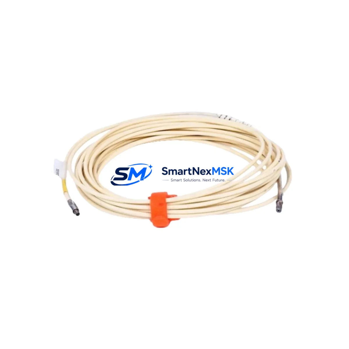
Bently Nevada 330101-00-14-10-10-02-05 3300 XL Spare: Spare Replacement & Industrial Downtime Risk Control
The Bently Nevada 330101-00-14-10-10-02-05 is an original proximity extension cable engineered for the 3300 XL Series vibration monitoring system — one of the most widely deployed condition monitoring platforms in rotating machinery applications across power generation, oil & gas, petrochemical, and heavy industrial facilities. When this cable degrades or fails, the entire vibration channel goes blind, stripping operators of critical shaft displacement and radial vibration data. Maintaining a certified spare on the shelf is not optional — it is a fundamental element of any serious predictive maintenance programme.
This 14-foot (approximately 4.27 m) extension cable connects the 3300 XL proximity transducer to the Proximitor sensor, completing the eddy-current measurement loop. The cable is precision-matched to the system’s electrical characteristics: any deviation in capacitance, impedance, or connector integrity will shift the gap voltage calibration and introduce measurement error. Only OEM-specification cables such as the 330101-00-14-10-10-02-05 guarantee the signal fidelity required for API 670-compliant machinery protection.
For maintenance engineers managing rotating equipment — turbines, compressors, pumps, gearboxes — the replacement workflow is straightforward: isolate the channel, verify the Proximitor output voltage at the junction box, swap the extension cable, re-confirm the gap voltage within the ±0.5 VDC tolerance band, and restore monitoring. Total downtime for a prepared technician with a verified spare is typically under 30 minutes. Without a spare, the same repair can extend to days of procurement lead time, leaving critical machinery running unprotected.
Procurement engineers sourcing this part should confirm the full part number — 330101-00-14-10-10-02-05 — against the installed cable tag and the system’s bill of materials. The 330101 series includes multiple length variants; the -00-14 segment designates the 14-foot configuration. Substituting an incorrect length will alter the system’s total cable capacitance and require recalibration of the Proximitor sensor, adding unnecessary commissioning time.
Spare Maintenance Table
| Parameter | Specification |
|---|---|
| Part Number | 330101-00-14-10-10-02-05 |
| Brand | Bently Nevada |
| Series | 3300 XL Proximity System |
| Product Type | Proximity Extension Cable |
| Cable Length | 14 ft (approx. 4.27 m) |
| Connector Type | MIL-C-5015 style, armoured coaxial |
| System Compatibility | Bently Nevada 3300 XL Proximitor Sensors (e.g. 330180, 330130) |
| Measurement Standard | API 670 compliant vibration monitoring |
| Operating Temperature | -40°C to +121°C (typical industrial field rating) |
| Installation Environment | Rotating machinery, turbine bearing housings, compressor trains |
| Maintenance Recommendation | Inspect connectors and armour sheath during every planned outage; replace at first sign of insulation degradation or connector corrosion |
| Origin | USA |
| Warranty | 12 Months |
| Pre-shipment Testing | Continuity, insulation resistance, and connector integrity verified before dispatch |
Maintenance Planning for Continuous Operation
A proximity extension cable failure rarely occurs in isolation. When performing a planned replacement of the 330101-00-14-10-10-02-05, a thorough maintenance engineer will use the opportunity to inspect the entire vibration measurement loop and the surrounding control cabinet infrastructure. Begin at the transducer end: check the 330900-series proximity probe for tip wear, contamination, or mechanical damage. Verify the probe mounting bracket torque and confirm the air gap is within the calibrated range — typically 1.0 to 1.5 mm for standard 8 mm probes.
At the Proximitor sensor — commonly a 330180-51-00 or 330130-040-01-00 depending on the installation — inspect the housing for moisture ingress and confirm the output voltage is within specification before and after cable replacement. The Proximitor’s power supply rail, typically supplied by a dedicated ±24 VDC instrument power module within the machinery protection rack, should be load-tested and its output ripple verified. A marginal power supply will cause intermittent gap voltage drift that mimics cable faults and wastes diagnostic time.
Inside the 3300 XL rack, inspect the monitor module — such as the 3300/16 or 3300/25 — for alarm relay contact condition and verify that the OK relay output is functioning correctly. The terminal input module (TIM) connections at the rack backplane should be re-torqued to specification. If the installation includes a 3500 Series rack alongside legacy 3300 XL hardware, confirm that the interconnecting signal cables and the system’s common ground reference are intact, as ground loops are a frequent source of spurious vibration alarms.
For facilities running DCS integration, verify the 4–20 mA or voltage output signal from the monitor to the DCS I/O card is within range after cable replacement. Signal isolators installed between the machinery protection system and the DCS should be tested for drift. Fuse holders and terminal blocks within the junction box — particularly those exposed to outdoor or high-humidity environments — should be inspected for corrosion and replaced proactively. Maintaining a small stock of spare terminal blocks, fuse elements, and connector backshells alongside the extension cable itself ensures that a single maintenance visit can resolve multiple latent failure points without a return trip.
Site Replacement Workflow
Replacing the 330101-00-14-10-10-02-05 in the field follows a structured sequence designed to minimise downtime and avoid recalibration errors. First, notify the control room and place the affected channel in bypass or inhibit mode within the 3300 XL monitor to prevent spurious trips during the swap. Document the existing gap voltage reading from the monitor front panel or the DCS historian before disconnecting any cables — this baseline is essential for post-replacement verification.
Disconnect the extension cable at both the probe junction box and the Proximitor sensor. Inspect both connectors for pin damage, corrosion, or contamination. Install the new 330101-00-14-10-10-02-05, ensuring connectors are fully seated and locking rings are tightened to the specified torque. Re-energise the Proximitor and allow a 2-minute warm-up period before reading the output voltage. Confirm the gap voltage matches the pre-replacement baseline within ±0.5 VDC. If the reading is outside tolerance, re-check the probe air gap before suspecting the cable.
Once the gap voltage is confirmed, remove the channel inhibit, verify the monitor’s OK status, and confirm alarm setpoints are active. Log the replacement in the equipment maintenance record with the new cable’s part number, serial number if applicable, and the post-replacement gap voltage. This documentation supports future fault analysis and demonstrates compliance with API 670 maintenance requirements.
For facilities transitioning from older 3300 Series hardware to the 3300 XL platform, the 330101-00-14-10-10-02-05 is directly compatible with the updated Proximitor sensors and does not require system reconfiguration, making it an effective drop-in replacement that extends the operational life of legacy monitoring installations without the cost of a full system upgrade.
Spare Parts Support FAQ
Q: What is the recommended spare parts stocking strategy for the 330101-00-14-10-10-02-05?
A: For facilities with four or more monitored machines using 3300 XL proximity systems, we recommend stocking a minimum of two extension cables per cable length variant in use. Extension cables are consumable items with a service life influenced by thermal cycling, vibration, and connector wear. A two-unit buffer ensures immediate availability for both planned outages and emergency replacements without waiting on procurement lead times.
Q: How do I verify compatibility before installation?
A: Confirm the full part number — 330101-00-14-10-10-02-05 — matches the cable tag on the installed unit and cross-reference against the Proximitor sensor model in use. The 330101 series is designed for use with Bently Nevada 3300 XL Proximitor sensors. If the installed Proximitor is a 3500/42 or other 3500 Series module, a different cable specification may be required. Contact our technical team with your Proximitor model number for confirmation before ordering.
Q: What pre-shipment testing is performed on this cable?
A: Every 330101-00-14-10-10-02-05 unit is tested for conductor continuity, insulation resistance, and connector mechanical integrity before dispatch. Units that do not meet OEM electrical specifications are quarantined and not shipped. A test record is available upon request for quality-critical installations.
Q: What does the 12-month warranty cover?
A: The 12-month warranty covers manufacturing defects, connector failure under normal operating conditions, and insulation integrity. It does not cover damage resulting from incorrect installation, mechanical abuse, or operation outside the specified temperature and environmental ratings. Warranty claims are supported with a replacement unit dispatched within 3 business days of fault confirmation.
© 2026 SMARTNEXMSK. All rights reserved.
Original Source: https://smartnexmsk.com
Contact: [email protected] | +86 18259474341



