
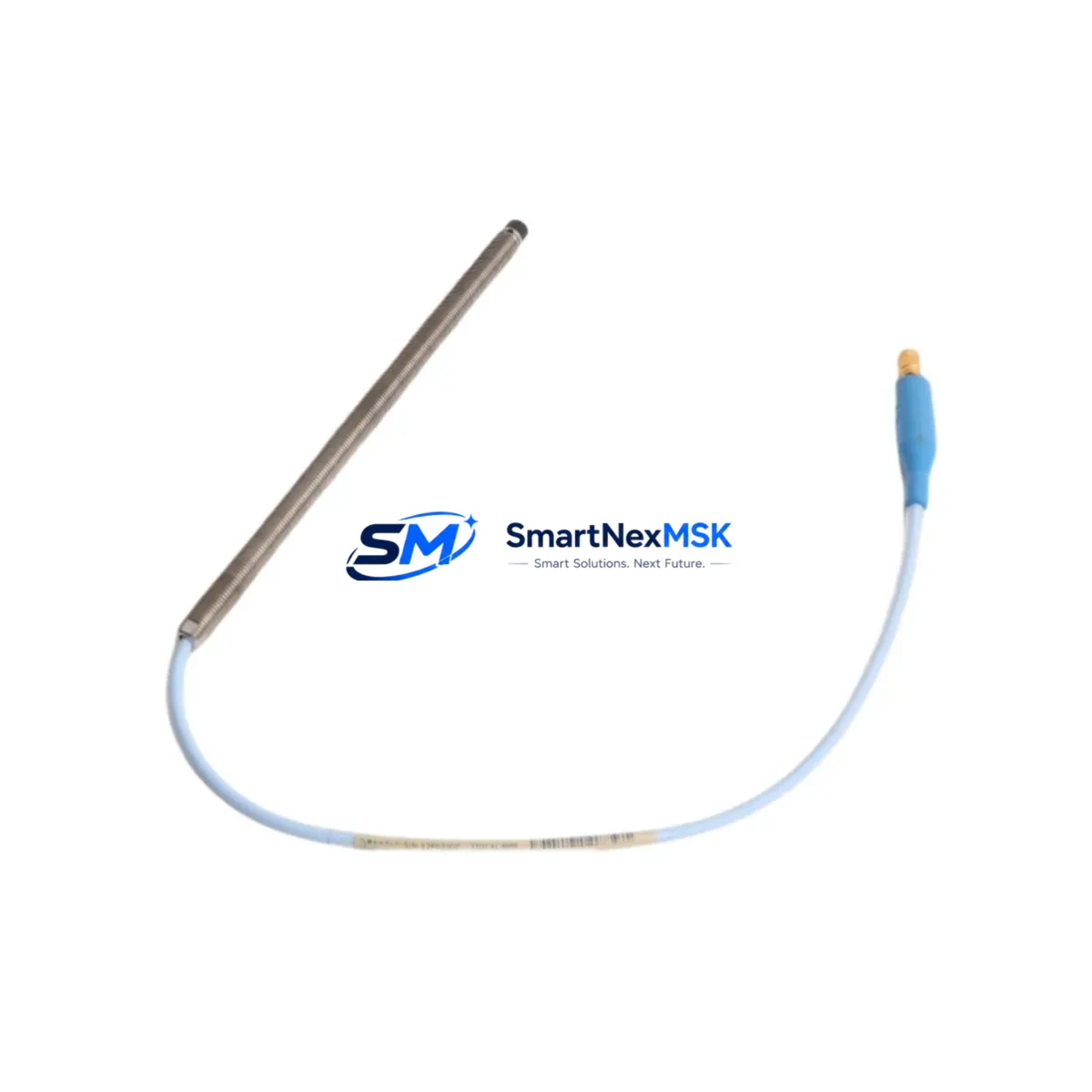
Bently Nevada 330101-00-76-10-02-05 Spare for 3300 XL Automation: Spare Replacement & Downtime Risk Control
The Bently Nevada 330101-00-76-10-02-05 is an original proximity transducer engineered for the 3300 XL Series vibration monitoring system — one of the most widely deployed condition monitoring platforms in rotating machinery applications across power generation, oil & gas, petrochemical, and heavy industrial facilities. When this transducer fails or degrades, the entire vibration channel goes offline, leaving critical rotating equipment — turbines, compressors, pumps, and fans — unprotected and potentially in violation of API 670 machinery protection standards.
Sourced as an original spare, the 330101-00-76-10-02-05 is fully compatible with the 3300 XL monitoring system architecture. It is tested prior to shipment, backed by a 12-month warranty, and available for rapid dispatch to minimize unplanned downtime. Whether you are executing a planned turnaround, responding to a channel fault alarm, or building a strategic spare parts inventory for long-term asset reliability, this transducer is a direct, drop-in replacement that restores full system functionality without reconfiguration.
Spare Maintenance Table
| Parameter | Specification / Detail |
|---|---|
| Part Number / SKU | 330101-00-76-10-02-05 |
| Brand | Bently Nevada |
| Series | 3300 XL |
| Product Type | Proximity Transducer (Eddy-Current) |
| Cable Length | 5m (standard extension cable configuration) |
| Probe Tip Diameter | 8 mm |
| Measurement Range | 0.25 mm – 2.25 mm (linear range) |
| Output Sensitivity | 7.87 V/mm (200 mV/mil) |
| Supply Voltage | -24 VDC (nominal) |
| Operating Temperature | -35°C to +121°C (probe); -35°C to +66°C (driver) |
| Target Material Compatibility | AISI 4140 steel (standard); other ferrous alloys per calibration |
| Connector Type | MIL-C-5015 style |
| Application Environment | Rotating machinery: turbines, compressors, pumps, fans |
| Compliance | API 670 compatible |
| Installation | Direct replacement; no reconfiguration required for 3300 XL monitors |
| Pre-Shipment Testing | Functional and output linearity verified before dispatch |
| Warranty | 12 Months from date of shipment |
| Origin | United States |
| Lead Time | In-stock; same-day or next-day dispatch available |
Maintenance Planning for Continuous Operation
Replacing the 330101-00-76-10-02-05 proximity transducer is rarely an isolated task. In a properly maintained 3300 XL monitoring loop, maintenance engineers should treat a transducer replacement as an opportunity to inspect and verify the condition of all associated components in the same vibration channel and control cabinet.
The 3300 XL extension cable (such as the 330130 series) runs between the probe and the driver and is a frequent source of signal degradation due to mechanical wear, connector corrosion, or chemical exposure in harsh plant environments. Always inspect the extension cable for continuity and insulation integrity during a transducer swap. Similarly, the 3300 XL proximitor/driver module (e.g., 330180 series) should be verified for correct bias voltage output — a drifting driver will produce erroneous gap voltage readings even with a new probe installed.
At the monitor level, the 3500/40M proximitor monitor or equivalent 3300 XL rack-mounted monitor card should be checked for firmware version compatibility and channel configuration. If the facility runs a dual-channel or redundant monitoring configuration, the paired transducer on the same shaft should also be inspected for wear or calibration drift. Procurement engineers building a spare parts kit should consider stocking the 3300 XL junction box and associated field wiring terminal blocks, as these are common failure points in outdoor or high-vibration installations.
For facilities running integrated machinery protection systems, the 3500 rack power supply module (e.g., 3500/15 or 3500/05) should be included in the inspection checklist — an unstable rack power supply can cause false channel trips and mask genuine transducer faults. If the monitoring system feeds into a DCS historian or safety instrumented system (SIS), verify that the 4–20 mA or relay output signals from the monitor are correctly received after the transducer replacement. Signal isolators or galvanic isolators in the signal chain should also be tested for correct isolation resistance and output accuracy.
For older installations where the 3300 XL system is approaching end-of-life, proactive replacement of the full transducer loop — probe, extension cable, and driver — is recommended to extend system service life and avoid cascading failures during critical production periods. Maintaining a minimum of two spare transducer assemblies per monitored machine train is a widely accepted best practice in rotating equipment reliability programs.
Site Replacement Workflow
Step 1 — Isolation and Permit: Obtain a work permit and isolate the monitoring channel at the 3300 XL monitor or 3500 rack. Do not de-energize the entire rack unless required — most 3300 XL monitors support channel bypass or inhibit mode to allow hot-swap maintenance without triggering a system trip.
Step 2 — Probe Removal: Disconnect the extension cable at the junction box or field connector. Unthread the probe from the mounting bracket, noting the gap distance (typically 1.0–1.5 mm for standard shaft monitoring). Record the original gap voltage for reference.
Step 3 — New Probe Installation: Install the 330101-00-76-10-02-05 replacement probe into the same mounting bracket. Set the gap distance to match the original specification using a non-ferrous feeler gauge or by monitoring the bias voltage output from the driver (target: approximately -10 VDC at nominal gap for standard 3300 XL configurations).
Step 4 — Cable Reconnection and Verification: Reconnect the extension cable. Verify the bias voltage at the monitor input is within the acceptable range (-10 VDC ± 1 VDC). Check that the channel is reading correctly in the monitor display and that no fault or not-OK indicators are active.
Step 5 — System Restore and Documentation: Remove the channel inhibit or bypass, restore normal monitoring, and document the replacement in the maintenance management system (CMMS). Record the new probe serial number, installation date, and gap voltage for future reference. Update the spare parts inventory to trigger reorder of a replacement unit.
This workflow ensures minimal downtime, maintains system compatibility, and provides a complete audit trail for compliance and reliability reporting.
Spare Parts Support FAQ
Q1: Is the 330101-00-76-10-02-05 a direct replacement for older 3300 XL proximity transducers?
Yes. The 330101-00-76-10-02-05 is designed as a direct, drop-in replacement within the 3300 XL transducer system. It maintains the same sensitivity (7.87 V/mm), connector type, and cable configuration as the standard 3300 XL probe family, ensuring full compatibility with existing 3300 XL drivers and monitors without requiring recalibration of the monitor card.
Q2: How is the transducer tested before shipment?
Each unit undergoes functional verification including bias voltage output check, linearity test across the specified measurement range, and connector integrity inspection before dispatch. A test report is available upon request. Units that do not meet original factory specifications are not shipped.
Q3: What is the recommended spare parts stocking strategy for this transducer?
For facilities with multiple monitored machine trains, we recommend maintaining a minimum of two spare 330101-00-76-10-02-05 transducer assemblies per site, along with at least one spare extension cable and one spare driver module. This ensures that a complete channel replacement can be executed within a single maintenance shift without waiting for parts procurement, which is critical for minimizing unplanned downtime on critical rotating equipment.
Q4: What does the 12-month warranty cover?
The 12-month warranty covers manufacturing defects, output specification non-conformance, and connector or cable assembly failures under normal operating conditions. It does not cover damage resulting from incorrect installation, mechanical impact, chemical exposure beyond rated limits, or operation outside the specified supply voltage range. Warranty claims are processed with priority, and replacement units are dispatched within 48 hours of claim approval.
© 2026 SMARTNEXMSK. All rights reserved.
Original Source: https://smartnexmsk.com
Contact: [email protected] | +86 18259474341



