
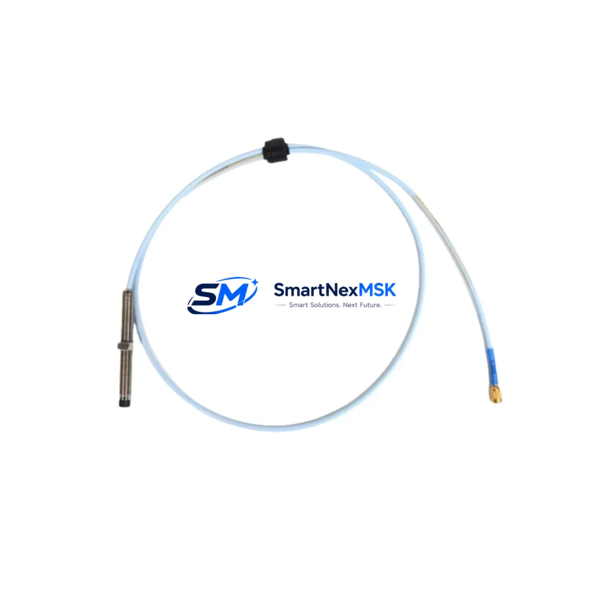
Bently Nevada 330101-33-66-10-02-05 Retrofit-Ready Proximity Probe for 3300 XL Control Systems
The Bently Nevada 330101-33-66-10-02-05 is an 8 mm eddy-current proximity probe engineered for the 3300 XL Series vibration monitoring platform. As legacy 3300 Series installations approach end-of-service milestones, this probe serves as the primary drop-in replacement for discontinued 330100 and 330101 variants, enabling plant engineers to restore full vibration monitoring capability without redesigning the existing wiring harness, conduit routing, or Proximitor® sensor mounting arrangement. Whether you are executing a planned turnaround, responding to an unplanned probe failure, or upgrading an aging machinery protection system, the 330101-33-66-10-02-05 delivers the electrical and mechanical compatibility required for a controlled, low-risk retrofit.
Upgrade Compatibility Table
| Parameter | Detail |
|---|---|
| SKU / Part Number | 330101-33-66-10-02-05 |
| Brand | Bently Nevada |
| Series Compatibility | Bently Nevada 3300 XL Series |
| Probe Diameter | 8 mm |
| Cable Length | 1.0 m probe + 5.0 m extension (armored) |
| Connector Interface | 3-pin MIL-C-5015 compatible; matches 3300 XL Proximitor® input |
| Replaces / Supersedes | 330101-33-66-10-02-00, 330100-33-66-10-02-05, legacy 3300 Series probes |
| Proximitor® Sensor Pairing | 3300 XL 8 mm Proximitor® (e.g. 330180-91-00) |
| Installation Requirement | No bracket modification; direct thread-in replacement (M10×1 thread) |
| Communication Compatibility | Analog 4–20 mA / voltage output; compatible with 3500 Series rack via signal conditioner |
| Commissioning Focus | Gap voltage verification (–10 VDC nominal), sensitivity calibration, OK relay check |
| Upgrade Path | Compatible with 3500/42M Proximitor®/Seismic Monitor for system-level upgrade |
| Warranty | 12 Months — covers manufacturing defects, electrical performance, and connector integrity |
Retrofit Planning for Existing Automation Systems
A successful retrofit of the 330101-33-66-10-02-05 into an operating plant begins well before the maintenance window opens. The first step is a full audit of the existing Proximitor® sensor — typically a 330180-91-00 or equivalent 3300 XL 8 mm unit — to confirm it remains within calibration tolerance. If the Proximitor® is also degraded, replacing both the probe and the sensor as a matched pair eliminates the risk of a second unplanned outage within the same maintenance cycle.
Next, verify the extension cable assembly. The 330130-045-00-00 armored extension cable is the standard pairing for this probe length configuration; inspect the BNC-to-MIL connector terminations for corrosion or mechanical damage before reuse. If the extension cable shows any sign of jacket cracking or shield continuity loss, replace it concurrently — field splicing is not recommended in high-vibration environments.
At the rack level, confirm that the 3500/42M Proximitor®/Seismic Monitor module or the 3300 XL monitor card assigned to this measurement point is configured for 8 mm probe sensitivity (7.87 V/mm). If the site is migrating from an older 3300 Series rack to a 3500 Series rack, the 3500/20 Rack Interface Module and the 3500/22M Transient Data Interface must be included in the bill of materials to maintain full data continuity with the existing System 1 condition monitoring software.
For plants running a Distributed Control System alongside the machinery protection system — for example, a DeltaV S-series controller or a Honeywell Experion PKS node — confirm that the 4–20 mA analog output from the Proximitor® is correctly mapped to the DCS I/O card before the probe is energized. Incorrect channel mapping is one of the most common causes of false OK-relay trips during commissioning. If the site uses a Modbus RTU or FOUNDATION Fieldbus gateway to bridge the 3500 rack to the DCS, verify the register map has not shifted due to rack slot changes during the upgrade.
HMI faceplate updates are frequently overlooked during probe replacements. If the control room runs a Wonderware InTouch or FactoryTalk View SE display, confirm that the vibration trend tag name and engineering-unit scaling on the affected measurement point still match the new probe’s output range after the swap. A mismatch here will not trigger a hard fault but will silently corrupt trend history, complicating future root-cause analysis.
Finally, document the as-found and as-left gap voltage readings — typically measured with a Bently Nevada 330930 proximitor tester or equivalent — and retain them in the equipment history file. This record is essential for warranty validation and for establishing the baseline used in the next scheduled calibration interval.
Downtime Control During System Migration
Minimizing unplanned downtime during a proximity probe replacement requires a structured pre-outage preparation protocol. Before the maintenance window begins, pre-stage the 330101-33-66-10-02-05 probe, the matched extension cable, and any required Proximitor® sensor so that the physical swap can be completed within a single shift. If the machine cannot be taken offline, coordinate with the control room to place the affected channel in bypass mode on the 3500 Series rack — this suppresses the OK relay output and prevents a spurious trip while the probe is disconnected, without disabling protection on adjacent channels.
Preserve the original PLC or DCS program logic throughout the migration. If the site uses a Rockwell Automation ControlLogix or CompactLogix controller to process the vibration signal downstream of the 3500 rack, do not modify the ladder logic or function block diagram during the probe swap. Any program changes should be staged, tested offline using Studio 5000 Logix Designer, and applied in a separate change window after the probe has been confirmed operational.
Once the new probe is installed and the gap voltage is set, perform a bump test to verify the measurement chain is live and the trend is updating correctly in the historian. Only after a clean bump test result should the bypass be removed and the channel returned to normal protection status. This sequence — bypass, swap, gap-set, bump test, restore — keeps the total exposure window to under two hours for a single-probe replacement on a well-prepared site, and eliminates the risk of a protection gap caused by a partially commissioned measurement point.
Retrofit Support FAQ
Q1: Is the 330101-33-66-10-02-05 a direct replacement for the 330101-33-66-10-02-00?
Yes. The -05 suffix denotes the armored cable jacket variant. The probe tip geometry, thread specification, sensitivity, and Proximitor® pairing are identical. No recalibration of the monitor card is required when substituting the -05 for the -00 variant, provided the extension cable length remains unchanged.
Q2: What commissioning checks are required after installation?
After physical installation, measure the gap voltage with the shaft stationary. The nominal target is –10.0 VDC ± 0.5 V at the recommended air gap of 1.27 mm (50 mil). Confirm the OK relay on the 3500/42M or 3300 XL monitor card is energized, and verify the vibration reading is within the expected baseline range for the machine at rest. Log as-found and as-left readings before closing the work order.
Q3: Can this probe be used with a 3500 Series rack without a signal conditioner?
The 330101-33-66-10-02-05 is natively compatible with the 3500/42M Proximitor®/Seismic Monitor when paired with the correct 3300 XL 8 mm Proximitor® sensor. No external signal conditioner is required for this combination. If integrating into a third-party protection system, a signal conditioner may be needed to match the output impedance and voltage range.
Q4: What does the 12-month warranty cover?
The 12-month warranty covers manufacturing defects, electrical performance within published specifications, and connector mechanical integrity. It does not cover damage resulting from incorrect gap setting, installation in an incompatible Proximitor® system, or physical impact. All units are function-tested prior to shipment; a test report is available upon request.
© 2026 SMARTNEXMSK. All rights reserved.
Original Source: https://smartnexmsk.com
Contact: [email protected] | +86 18259474341



