
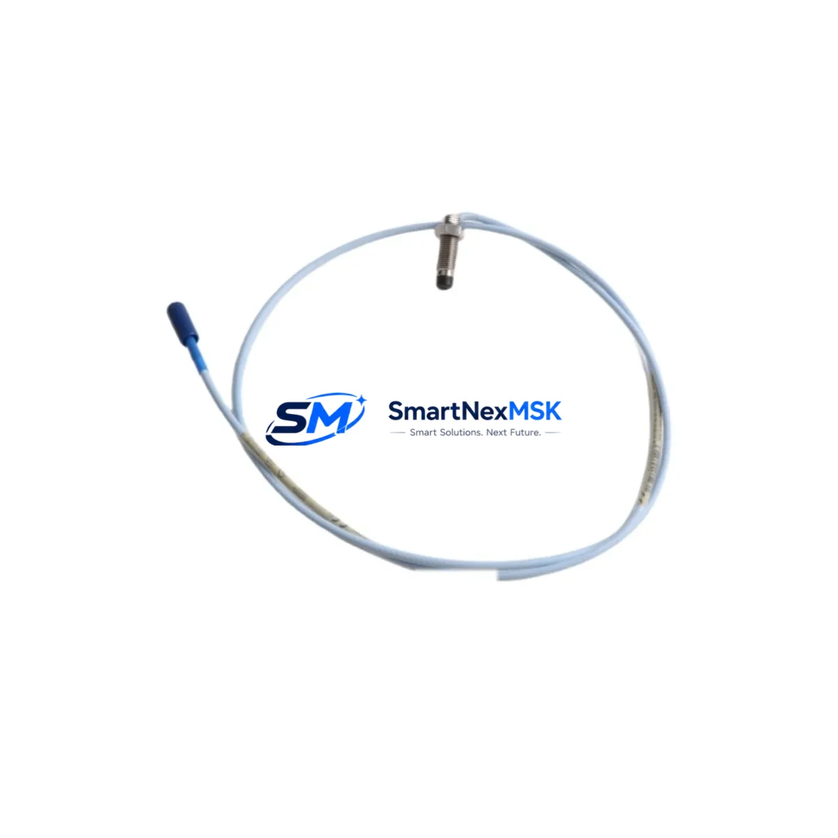
Bently Nevada 330101-40-60-05-02-CN Retrofit-Ready Proximity Probe for 3300 XL Control Systems
The Bently Nevada 330101-40-60-05-02-CN is an 8mm eddy-current proximity probe designed for the 3300 XL Series vibration monitoring platform. This probe is widely deployed in turbomachinery protection systems across power generation, oil & gas, petrochemical, and heavy industrial facilities. As the original 3300 Series reaches end-of-life and spare parts become increasingly scarce, the 330101-40-60-05-02-CN serves as the primary retrofit-ready replacement for legacy 3300 standard probes, offering full signal compatibility with existing Proximitor® sensor drivers, junction boxes, and rack-mounted monitors.
When planning a retrofit from an older 3300 standard probe to the 3300 XL platform, engineers must verify several critical parameters before commissioning. The probe cable length of this variant is 5 meters (extension cable) + 2 meters (probe), with a total system length of 5m, which must match the calibrated gap voltage curve stored in the paired 330180-X0-05 or 330130-040-00-00 Proximitor® sensor. Mismatched cable lengths will shift the linear range and introduce measurement error at the monitor level. Always confirm the Proximitor® part number and its calibrated range before swapping probes in the field.
Terminal wiring for the 330101-40-60-05-02-CN follows the standard Bently Nevada three-wire convention: shield drain, center conductor (signal), and outer conductor (common). When migrating from older 3300 standard probes installed in legacy 3300/16-channel monitor or 3300/20-channel monitor racks, verify that the existing field wiring uses the correct conductor gauge and that the junction box terminal blocks are rated for the signal voltage range (typically –24 VDC bias). Corroded or undersized terminals are a common source of noise after retrofit and should be replaced during the same maintenance window.
Upgrade Compatibility Table
| Parameter | Legacy 3300 Standard Probe | 330101-40-60-05-02-CN (3300 XL) |
|---|---|---|
| Probe Diameter | 8mm | 8mm |
| Probe Cable Length | 5m (varies by suffix) | 5m extension + 2m probe |
| Proximitor® Compatibility | 3300/05-05 Proximitor® | 330180-X0-05 / 330130-040-00-00 |
| Monitor Rack Compatibility | 3300/16, 3300/20 monitors | 3500/42M, 3500/40M, 3300 XL monitors |
| Signal Output Range | –24 VDC (200 mV/mil) | –24 VDC (200 mV/mil) |
| Installation Thread | M10 × 1.0 | M10 × 1.0 |
| Communication Protocol | Analog (4–20 mA / voltage) | Analog (4–20 mA / voltage) |
| Retrofit Recommendation | Replace probe + Proximitor® as a matched set | Direct drop-in with matched Proximitor® |
| Commissioning Note | Re-gap to 1.0 mm nominal; verify gap voltage | Re-gap to 1.0 mm nominal; verify gap voltage |
| Warranty | — | 12-Month Warranty |
Retrofit Planning for Existing Automation Systems
A successful retrofit of the 330101-40-60-05-02-CN into an existing turbomachinery protection system requires a structured approach that accounts for the full signal chain. The probe does not operate in isolation — it is part of a matched system that includes the 330130-040-00-00 extension cable, the 330180-51-05 Proximitor® sensor, and the rack-mounted monitor card such as the 3500/42M Proximitor®/Seismic Monitor or the legacy 3300/16-channel vibration monitor.
Before pulling the old probe, document the existing gap voltage at the Proximitor® output terminal. The nominal gap for an 8mm probe is 1.0 mm, corresponding to approximately –10.0 VDC on a standard 200 mV/mil scale. After installing the 330101-40-60-05-02-CN, re-gap the probe to the same nominal distance and verify the output voltage falls within the linear range specified on the Proximitor® calibration label. If the system uses a 3500/20 rack power supply or a 3500/15 power supply module, confirm that the supply voltage is stable at –24 VDC before energizing the new probe circuit.
For facilities migrating from a legacy 3300 Series rack to a 3500 Series rack, the retrofit scope typically expands to include replacement of the 3500/01 rack backplane, installation of new 3500/22M transient data interface cards, and reconfiguration of the System 1 or System 1 Evolution software database to reflect the new monitor addresses and channel assignments. HMI screens built on the legacy platform will require tag remapping to align with the new rack’s Modbus or Ethernet/IP register map. Plan for a minimum of four hours of software configuration time per rack during the migration window.
I/O expansion during the same retrofit window is common. Many facilities take the opportunity to add 3500/64M process variable monitor cards for temperature and pressure inputs, or to install 3500/50 tachometer modules for speed and phase reference signals. These additions require careful slot assignment within the 3500 rack to avoid address conflicts with existing vibration channels. The 3500/22M transient data interface should always occupy a dedicated slot adjacent to the monitor cards it serves.
Downtime Control During System Migration
Minimizing unplanned downtime during a proximity probe retrofit requires pre-staging all replacement components before the maintenance window opens. For the 330101-40-60-05-02-CN, this means having the matched 330180-51-05 Proximitor® sensor and 330130-040-00-00 extension cable bench-tested and gap-verified before the machine is taken offline. Use a bench-top target simulator or a flat steel target to confirm the probe’s linear range and output voltage before installation.
During the outage, follow a parallel-swap strategy: install the new probe in the mounting boss, route the extension cable to the junction box, and connect to the Proximitor® before removing the old probe from the monitor input. This approach allows the technician to verify signal continuity at the Proximitor® output before committing to the final cutover. Once the new probe is confirmed live and gapped correctly, the old probe circuit can be safely de-energized and removed.
Program logic in the 3500 Series monitor is stored in non-volatile memory and is not affected by probe replacement, provided the channel configuration (sensitivity, full-scale range, alert and danger setpoints) remains unchanged. If the replacement probe has a different sensitivity coefficient — for example, if the legacy probe was calibrated for a non-standard target material — the monitor channel must be reconfigured using the Rack Configuration Software (RCS) before the machine is returned to service. Always perform a final system functional test, including alert and danger relay verification, before releasing the machine to operations.
Retrofit Support FAQ
Q1: Is the 330101-40-60-05-02-CN a direct drop-in replacement for the legacy 3300 standard 8mm probe?
A: Yes, provided the replacement is paired with a compatible 3300 XL Proximitor® sensor (such as the 330180-51-05) and the extension cable length matches the Proximitor® calibration. The probe thread (M10 × 1.0), mounting boss diameter, and signal output scale (200 mV/mil) are identical to the legacy 3300 standard probe.
Q2: What wiring changes are required when retrofitting this probe into an existing junction box?
A: No wiring changes are required at the junction box if the existing field cable is in good condition and the terminal block assignments follow the standard Bently Nevada three-wire convention. Inspect the shield drain connection and verify continuity from the junction box to the Proximitor® input terminals before energizing the circuit.
Q3: Does this probe support Modbus or Ethernet/IP communication for integration with a DCS or SCADA system?
A: The 330101-40-60-05-02-CN is an analog proximity probe and does not itself support digital communication protocols. Digital output (Modbus RTU, Modbus TCP, or Ethernet/IP) is provided by the rack-mounted monitor card — such as the 3500/42M or 3500/22M — which converts the analog probe signal into a digital process variable for transmission to the DCS or SCADA host.
Q4: What does the 12-month warranty cover, and is pre-shipment testing performed?
A: Every 330101-40-60-05-02-CN unit shipped by SMARTNEXMSK undergoes pre-shipment functional testing, including gap voltage verification and cable continuity check. The 12-month warranty covers manufacturing defects and signal performance within the specified linear range. Units showing physical damage from improper installation or target contact are not covered. Warranty claims are processed within 5 business days of receipt of the returned unit.
© 2026 SMARTNEXMSK. All rights reserved.
Original Source: https://smartnexmsk.com
Contact: [email protected] | +86 18259474341



