
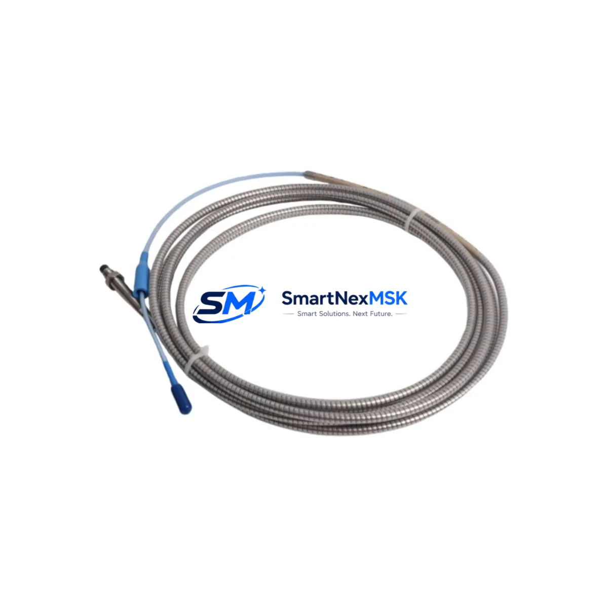
Bently Nevada 330102-05-40-05-02-05 Retrofit-Ready 5mm Proximity Transducer for 3300 XL Control Systems
The Bently Nevada 330102-05-40-05-02-05 is a 5mm proximity transducer engineered for seamless integration into existing 3300 XL machinery protection systems. Designed to serve as a direct retrofit replacement for discontinued or aging transducer assemblies, this unit supports smooth migration from legacy Bently Nevada configurations without requiring full system overhaul. Whether you are upgrading a turbine monitoring rack, replacing a failed sensor in a compressor protection loop, or modernizing a control cabinet that has been in service for over a decade, the 330102-05-40-05-02-05 delivers the signal integrity and mechanical compatibility your application demands.
Industrial facilities running continuous processes — including power generation, petrochemical refining, and rotating machinery operations — rely on uninterrupted vibration and position monitoring. When a proximity transducer reaches end-of-life or becomes unavailable through standard supply channels, the replacement process must be executed with precision. This product is stocked and tested to support exactly that scenario: verified compatibility, documented wiring equivalence, and a 12-month warranty covering both parts and workmanship.
Upgrade Compatibility Table
| Parameter | Details |
|---|---|
| SKU / Part Number | 330102-05-40-05-02-05 |
| Series Compatibility | Bently Nevada 3300 XL Series |
| Transducer Gap Range | 5mm nominal sensing range |
| Connector / Interface | Standard 3300 XL coaxial connector; compatible with existing extension cable assemblies (e.g., 330130 series) |
| Mounting | Threaded body; direct replacement for existing bracket and housing configurations |
| Signal Output | -18 VDC nominal; compatible with 3300 XL monitor inputs including 3300/16 and 3300/20 series cards |
| Communication Compatibility | Passive analog signal; no protocol migration required; compatible with existing 4–20 mA and voltage-output monitor cards |
| Replacement Recommendation | Direct drop-in for 330102-05-xx-xx-xx variants; verify gap calibration after installation |
| Commissioning Notes | Re-calibrate gap voltage at installation; verify OK LED status on monitor card; confirm alarm and danger setpoints in system configuration |
| Warranty | 12 months from date of shipment; covers manufacturing defects and signal performance |
Retrofit Planning for Existing Automation Systems
Replacing a proximity transducer in a live 3300 XL system requires careful coordination across multiple components. Before removing the existing 330102-05-40-05-02-05 or its predecessor, engineers should document the current gap voltage reading — typically between -10 VDC and -18 VDC — and confirm the extension cable assembly in use. The 330130-080-00-00 extension cable is the most common pairing in this configuration, and its condition should be inspected for continuity and shielding integrity before reuse.
The proximitor or oscillator-demodulator in the loop — often a 3300 XL 8mm or 5mm proximitor such as the 330180-91-00 — must be verified for compatibility with the replacement transducer’s sensitivity specification (typically 200 mV/mil). If the proximitor has been in service for an extended period, this is an appropriate time to evaluate whether it should also be replaced as part of the retrofit scope.
On the monitor side, confirm that the 3300/16-02-01-01-00-00 or equivalent monitor card is configured for the correct transducer type and gap range. Many legacy installations use the 3500 series rack alongside 3300 XL field devices during phased migration programs; in these cases, the 3500/42M proximity monitor module may already be installed in the rack, and the transducer signal routing should be verified against the I/O termination block wiring diagram.
For facilities that have begun migrating toward the Bently Nevada 3500 platform, the 330102-05-40-05-02-05 remains fully compatible as a field device during the transition period. The 3500/22M transient data interface and the 3500/40M proximitor I/O module both accept standard 3300 XL transducer signals, allowing the field wiring to remain unchanged while the rack and software infrastructure is upgraded. This approach significantly reduces the scope of field work and minimizes exposure to installation errors during the migration window.
Control cabinet upgrades involving this transducer should also account for the power supply feeding the proximitor loop. The 3300 XL system typically draws from a -24 VDC rail; verify that the cabinet power supply — whether a dedicated Bently Nevada power supply module or a third-party DIN-rail unit — can sustain the load with the new transducer installed. Terminal block wiring should be inspected and re-torqued to manufacturer specifications, particularly in high-vibration environments where terminal loosening is a known failure mode.
If the installation involves an HMI running a Bently Nevada System 1 or System 1 Evolution software platform, no screen reconfiguration is typically required for a like-for-like transducer replacement. However, if the replacement is part of a broader channel reassignment or rack reconfiguration, the System 1 database tag mapping and alarm group assignments should be reviewed and updated before returning the machine to service.
Downtime Control During System Migration
Minimizing unplanned downtime during a proximity transducer replacement is a primary concern for operations and maintenance teams. The 330102-05-40-05-02-05 is stocked for immediate shipment, which eliminates the lead-time uncertainty that often extends planned outage windows when sourcing discontinued or hard-to-find components.
For planned replacements, the recommended approach is to pre-stage the new transducer, extension cable, and any associated proximitor in the maintenance shop before the outage begins. Bench-test the assembly using a calibration target to confirm the gap voltage curve matches the expected sensitivity specification. This pre-verification step allows the field team to install a confirmed-good assembly and reduces the risk of a second outage caused by a defective replacement unit.
During the outage, the original program logic in the DCS or safety system does not require modification for a direct transducer replacement. The monitor card continues to receive the same signal type and range, and the alarm and danger setpoints remain valid provided the new transducer is gapped correctly. If the machine has a bypass key switch or software bypass capability in the 3300 or 3500 monitor, activate the bypass for the affected channel before disconnecting the field wiring to prevent spurious trips during the installation process.
After installation, perform a static gap check with the machine at rest, then a dynamic check during run-up to confirm the vibration signal is clean and within expected amplitude. Log the as-left gap voltage in the maintenance record and update the equipment history file. The 12-month warranty on this unit provides coverage throughout the initial post-installation operating period, giving maintenance teams confidence in the reliability of the replacement.
Retrofit Support FAQ
Q: Is the 330102-05-40-05-02-05 a direct replacement for other 330102 series variants?
A: The 330102 series uses a standardized suffix structure where the digits indicate cable length, connector type, and temperature rating. The -05-40-05-02-05 configuration specifies a 5mm gap range, 40-inch armored cable, standard connector, and extended temperature rating. Other 330102 variants with different cable lengths or connector configurations may be mechanically interchangeable at the sensing tip but will differ in cable routing. Always verify the full part number against your installation drawing before ordering.
Q: What commissioning steps are required after installation?
A: After mechanical installation, connect the extension cable and proximitor, then apply power to the loop. Measure the DC gap voltage at the proximitor output with the target at the nominal gap distance (typically 50 mils / 1.27 mm for a 5mm transducer). Adjust the mounting position until the gap voltage reads within the linear range specified on the transducer calibration curve. Confirm the OK relay on the monitor card is energized, then verify alarm and danger setpoints are active. Document the as-left gap voltage and sign off the work order before returning the machine to service.
Q: Can this transducer be used with a 3500 series rack during a phased migration?
A: Yes. The 330102-05-40-05-02-05 is compatible with 3500 series monitor cards that accept standard 3300 XL transducer inputs, including the 3500/40M and 3500/42M modules. No field wiring changes are required when migrating the rack infrastructure while retaining existing field devices. Confirm the monitor card configuration in the 3500 Rack Configuration Software matches the transducer sensitivity and gap range.
Q: What does the 12-month warranty cover?
A: The 12-month warranty covers manufacturing defects, signal performance outside published specifications, and mechanical integrity of the transducer body and connector. It does not cover damage resulting from incorrect installation, over-range mechanical contact, or exposure to environments outside the rated temperature and chemical resistance specifications. Warranty claims are processed with proof of purchase and a description of the failure mode; replacement units are shipped from stock to minimize downtime.
© 2026 SMARTNEXMSK. All rights reserved.
Original Source: https://smartnexmsk.com
Contact: [email protected] | +86 18259474341



