
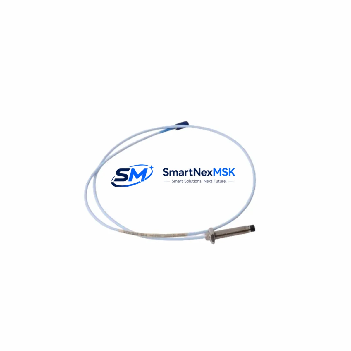
Bently Nevada 330103-00-04-10-01-00 3300 XL Extension Cable 4m: Retrofit-Ready Proximity Extension for Legacy Vibration Monitoring Systems
The Bently Nevada 330103-00-04-10-01-00 is a 4-meter proximity extension cable engineered for the 3300 XL Series vibration monitoring platform. As legacy Bently Nevada systems approach end-of-support cycles, this cable serves as a critical retrofit component for facilities maintaining continuous machinery protection on rotating equipment such as turbines, compressors, pumps, and gearboxes. Whether you are replacing a failed cable in an emergency shutdown scenario or executing a planned control system upgrade, the 330103-00-04-10-01-00 provides a verified drop-in solution that preserves signal integrity across the full 3300 XL measurement chain.
This extension cable is designed to bridge the 3300 XL proximity transducer — typically a 330101 or 330103 series probe — to the 3300 XL proximitor/seismic transducer module mounted in the rack. The cable maintains the precise electrical characteristics required by the 3300 XL signal conditioning circuitry, including correct impedance matching, shielding continuity, and connector compatibility with the standard TNC-to-TNC interface used throughout the 3300 XL platform.
Upgrade Compatibility Table
| Parameter | Details |
|---|---|
| SKU / Part Number | 330103-00-04-10-01-00 |
| Series Compatibility | Bently Nevada 3300 XL Series |
| Cable Length | 4 metres (13.1 ft) |
| Connector Interface | TNC male / TNC female — standard 3300 XL mating |
| Compatible Probes | 330101, 330103 series proximity transducers |
| Compatible Proximitor Modules | 3300 XL 8mm, 11mm, 14mm proximitor/seismic modules |
| Installation Requirement | No rack modification required; direct cable swap |
| Communication / Signal Type | Eddy-current analog signal; passive cable — no firmware dependency |
| Replacement Recommendation | Direct drop-in for OEM 330103-00-04-10-01-00; verify total cable system length against proximitor gap voltage specification |
| Commissioning Focus | Gap voltage verification at proximitor output; OK relay status confirmation; signal noise floor check |
| Warranty | 12-Month Warranty — functional and dimensional conformance guaranteed |
Retrofit Planning for Existing Automation Systems
Replacing a proximity extension cable in an operating plant requires careful coordination across multiple system layers. The 330103-00-04-10-01-00 sits within a measurement chain that typically includes a 330101 or 330103 proximity probe, the extension cable itself, and a 3300 XL proximitor module — such as the 3300/16 or 3300/20 — housed in a 3300 XL rack assembly. Before pulling the failed cable, technicians should document the existing gap voltage reading at the proximitor output terminal, which for an 8mm probe system should fall within the –10 VDC to –18 VDC OK window. This baseline reading confirms probe-to-target gap and allows rapid re-verification after the new cable is installed.
In facilities running the System 1 condition monitoring software or the older ADRE 408 DSPi data acquisition platform, the measurement point configuration — including transducer scale factor, full-scale range, and alert/danger setpoints — is stored at the software level and does not need to be re-entered following a cable swap. However, if the replacement is part of a broader migration from the legacy 3300 Series to the current 3500 Series rack architecture, engineers must account for differences in proximitor module pinout, rack backplane addressing, and the 3500/42M or 3500/40M monitor card configuration. In that scenario, the extension cable specification may change, and the 330103-00-04-10-01-00 should be evaluated against the new total cable system length requirement.
For sites upgrading control cabinet wiring in parallel with the cable replacement, it is common to simultaneously service the 3300 XL power supply module — typically a 3300/05 or equivalent — to ensure stable –24 VDC bias voltage is maintained across all proximitor channels. Loose terminal blocks on the power distribution rail are a frequent source of intermittent OK relay trips during post-replacement commissioning and should be inspected and re-torqued as part of the retrofit procedure. If the plant also operates Bently Nevada 3500/22M transient data interface cards or 3500/92 communication gateway modules for Modbus or Ethernet/IP integration with the DCS, verify that the communication link remains active throughout the cable swap to avoid nuisance alarms at the control room HMI.
Sites that use a Rockwell Automation ControlLogix or CompactLogix PLC to process 4–20 mA outputs from the 3300 XL monitors should confirm that the analog input module — such as a 1756-IF16 or 1769-IF4 — continues to receive valid signals during the transition. If the HMI screens built in FactoryTalk View SE or Wonderware InTouch display vibration trend data sourced from the 3300 XL, coordinate with the control room operator to suppress the affected measurement point alarm during the brief cable disconnection window to prevent a spurious shutdown signal from propagating to the safety instrumented system.
Downtime Control During System Migration
Minimizing unplanned downtime is the primary operational concern when replacing proximity extension cables on running machinery protection systems. The recommended approach is to pre-stage the 330103-00-04-10-01-00 replacement cable, verify its physical dimensions and connector condition before the maintenance window opens, and prepare a gap voltage measurement kit — typically a calibrated digital multimeter and a non-conductive feeler gauge — so that re-commissioning can begin immediately after the cable is seated.
Where the plant safety management system permits, place the affected 3300 XL monitor channel in bypass mode through the System 1 software or via the front-panel bypass switch on the 3300/16 monitor card before disconnecting the cable. This prevents the open-circuit condition during cable removal from triggering a danger relay output and initiating an unnecessary machine trip. Maintain a written log of the bypass activation time, the technician name, and the expected restoration time in accordance with your site’s management of change procedure.
After installing the 330103-00-04-10-01-00, restore the gap voltage to within the OK band, confirm the OK LED on the proximitor module is illuminated, remove the bypass, and verify that the System 1 or ADRE trend display shows a stable, noise-free vibration signal before returning the machine to normal monitored operation. The entire cable swap — from bypass activation to bypass removal — can typically be completed in under 30 minutes by a trained instrumentation technician, keeping production impact to an absolute minimum.
Retrofit Support FAQ
Q1: Is the 330103-00-04-10-01-00 a direct replacement for the original Bently Nevada part?
Yes. This cable is manufactured to the same dimensional and electrical specification as the original OEM part. The TNC connector interface, cable impedance, and shielding construction are fully compatible with the 3300 XL proximitor module and 330103 series proximity probe. No adapters or wiring modifications are required for a like-for-like swap.
Q2: What commissioning checks are required after installation?
After seating the cable, measure the DC gap voltage at the proximitor output terminal and confirm it falls within the –10 VDC to –18 VDC OK window for an 8mm probe system (adjust range for 11mm or 14mm probe configurations). Confirm the OK relay is energized, check the vibration signal on the System 1 or ADRE display for noise or offset anomalies, and verify that no latched danger alarms are present before removing the channel bypass.
Q3: Can this cable be used in a migration from the 3300 Series to the 3500 Series platform?
The 330103-00-04-10-01-00 is specified for the 3300 XL platform. If you are migrating to the 3500 Series, the total cable system length and connector specification must be re-evaluated against the 3500 Series proximitor requirements. In many cases a new cable assembly matched to the 3500/42M or 3500/40M monitor card specification will be required. Contact our technical team for a migration-specific cable recommendation.
Q4: What warranty coverage is provided?
All units ship with a 12-month warranty covering functional performance and dimensional conformance. Each cable undergoes pre-shipment continuity, insulation resistance, and connector integrity testing. If a defect is identified within the warranty period, we provide a replacement unit or full refund. Warranty claims are processed within 5 business days of receipt of the returned item.
© 2026 SMARTNEXMSK. All rights reserved.
Original Source: https://smartnexmsk.com
Contact: [email protected] | +86 18259474341



