
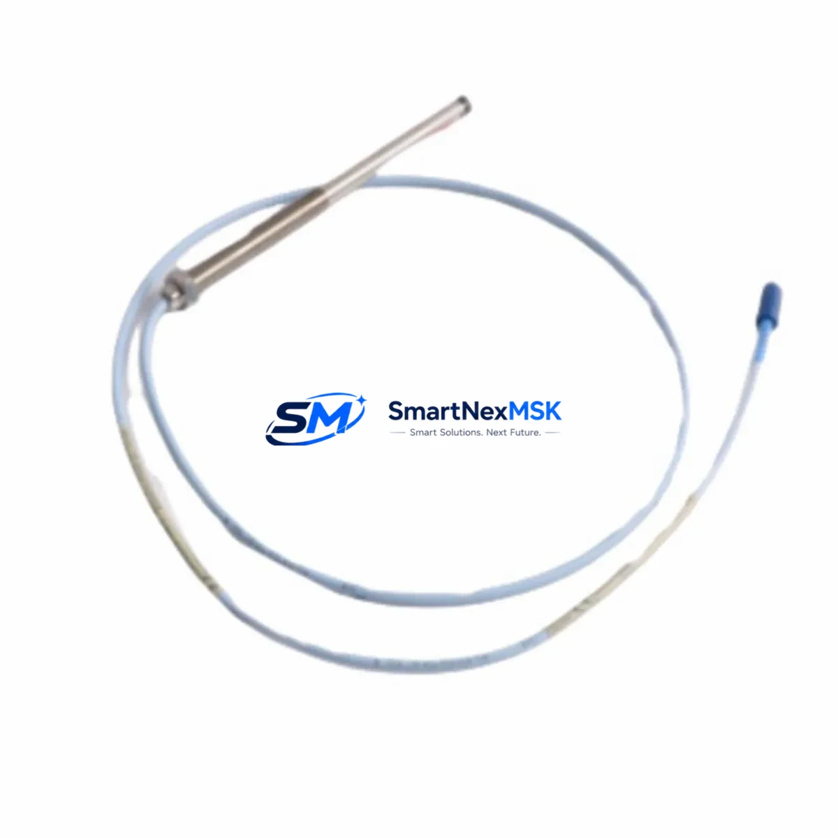
Bently Nevada 330103-00-08-10-02-05 Maintenance-Ready Spare 3300 XL: Spare Replacement & Industrial Downtime Risk Control
The Bently Nevada 330103-00-08-10-02-05 is an original 8mm eddy-current proximity probe engineered for the 3300 XL continuous vibration monitoring system. In rotating machinery protection — turbines, compressors, pumps, and gearboxes — this probe is a front-line sensor responsible for detecting shaft radial vibration, axial position, and differential expansion. When this component degrades or fails, the entire machinery protection loop is compromised, creating unplanned downtime risk that can cascade across a production line.
For maintenance engineers and spare parts procurement teams managing critical rotating equipment, stocking a verified replacement of the 330103-00-08-10-02-05 is not optional — it is a fundamental element of any predictive maintenance or reliability-centered maintenance (RCM) program. This listing provides an original, tested spare with a 12-month warranty, ready for immediate dispatch to minimize mean time to repair (MTTR).
Spare Maintenance Table
| Parameter | Specification |
|---|---|
| Part Number / SKU | 330103-00-08-10-02-05 |
| Brand | Bently Nevada |
| Series | 3300 XL |
| Probe Type | Eddy-Current Proximity Probe (8mm) |
| Cable Length | 1.0 m (integral cable) |
| Extension Cable Compatibility | 3300 XL Extension Cable (330130 series) |
| Driver / Proximitor Compatibility | 3300 XL 8mm Proximitor Sensor (330180 series) |
| Measurement Range | 0.25 mm – 2.26 mm (linear range) |
| Sensitivity | 7.87 V/mm (200 mV/mil) |
| Supply Voltage | -24 VDC (nominal) |
| Operating Temperature | -35°C to +177°C (probe tip) |
| Target Material | AISI 4140 steel or equivalent ferromagnetic alloy |
| Ingress Protection | IP67 (probe body) |
| Mounting Thread | M10 × 1.0 |
| Application Environment | Turbines, compressors, pumps, gearboxes, motors |
| Condition | Original spare, factory-equivalent |
| Pre-shipment Testing | Functional output and sensitivity verified |
| Warranty | 12 months from date of shipment |
| Origin | USA |
Maintenance Planning for Continuous Operation
When a 330103-00-08-10-02-05 proximity probe is scheduled for replacement — whether during a planned outage, a condition-based maintenance trigger, or an emergency fault response — experienced maintenance engineers know that the probe itself is rarely the only component that requires attention. A thorough inspection of the complete measurement chain and surrounding control cabinet components is essential to restore full system integrity and prevent repeat failures.
Begin with the 3300 XL Extension Cable (330130 series): inspect the connector pins, cable jacket, and armored sheath for mechanical damage, corrosion, or insulation breakdown. Extension cables routed through hot zones near turbine casings are particularly susceptible to thermal degradation. Next, verify the 3300 XL Proximitor Sensor (330180 series) — the signal conditioning module that converts the probe’s raw oscillator output into a calibrated DC voltage. A drifting or failed Proximitor will produce erroneous vibration readings even with a new probe installed, so bench-test or swap the Proximitor as part of the same maintenance window.
At the control cabinet level, inspect the 3300 XL Monitor (3300/16 or 3300/20 series) input cards for alarm setpoint integrity and channel configuration. Confirm that the terminal strip and field wiring connecting the Proximitor output to the monitor input are free of loose terminations, oxidation, or ground loops — a common source of noise that mimics real vibration signals. If the system uses a 3300 XL Power Supply module, verify that the -24 VDC rail is within tolerance; an under-voltage condition will shift the probe’s operating point and invalidate calibration.
For facilities running integrated DCS or safety instrumented systems (SIS), check the 4–20 mA output signal isolator or signal conditioner that interfaces the 3300 XL monitor output to the DCS I/O card. Signal isolators from the 3300 XL accessory range or equivalent DIN-rail isolators should be inspected for drift. If the plant uses a Bently Nevada System 1 Evolution software platform for online machinery diagnostics, confirm that the channel configuration and gap voltage setpoints are updated to match the replacement probe’s calibration data.
Additionally, review the junction box and conduit seals at the probe mounting location for moisture ingress — a leading cause of premature probe failure in outdoor or wash-down environments. Where applicable, inspect the thrust bearing clearance and shaft target area surface finish, as a corroded or scored shaft surface will degrade measurement accuracy regardless of probe condition. Stocking companion spares such as the 330130-080-00-00 extension cable and 330180-X1-05 Proximitor alongside the 330103-00-08-10-02-05 probe ensures that a complete channel replacement can be executed within a single maintenance shift, minimizing total downtime exposure.
Site Replacement Workflow
Step 1 — Isolation and Lockout/Tagout (LOTO): Follow plant LOTO procedures for the affected machinery. Do not rely solely on the monitor’s bypass function; physically isolate the machine before probe removal.
Step 2 — Gap Voltage Verification: Before removing the old probe, record the existing gap voltage (typically -10 VDC ± 1 VDC for an 8mm probe at nominal gap). This baseline confirms whether the original probe had drifted out of calibration prior to failure.
Step 3 — Probe Removal: Use the correct spanner to unthread the M10 × 1.0 probe body. Avoid applying torque to the cable or connector. Inspect the probe tip and mounting boss for thread damage or contamination.
Step 4 — New Probe Installation: Install the 330103-00-08-10-02-05 replacement probe. Set the gap to the manufacturer-specified distance (typically 1.0 mm ± 0.1 mm for the linear midpoint) using a non-ferromagnetic feeler gauge. Torque to specification.
Step 5 — System Reconnection and Gap Calibration: Reconnect the extension cable and Proximitor. Power up the -24 VDC supply and verify the gap voltage at the monitor input. Adjust gap as needed to achieve the target DC output. Confirm alarm and danger setpoints are active.
Step 6 — Functional Test Before Return to Service: Perform a slow-roll check or bump test to confirm the channel responds correctly to shaft movement. Log the as-left gap voltage and sensitivity in the maintenance management system (CMMS) for future reference.
This workflow is compatible with legacy 3300 series installations and current 3300 XL deployments, enabling a direct drop-in replacement without system reconfiguration in most applications.
Spare Parts Support FAQ
Q1: Is the 330103-00-08-10-02-05 compatible with older Bently Nevada 3300 (non-XL) systems?
The 330103-00-08-10-02-05 is designed and calibrated for the 3300 XL system architecture. While the physical connector and thread dimensions may be similar to earlier 3300 series probes, the sensitivity calibration (7.87 V/mm) and system matching are optimized for 3300 XL Proximitor sensors. Cross-compatibility with non-XL monitors should be verified against the specific monitor’s input specification before installation. Contact our technical team for compatibility confirmation if your system predates the XL platform.
Q2: What pre-shipment testing is performed on this spare?
Every 330103-00-08-10-02-05 unit is functionally tested prior to dispatch. Testing includes verification of the probe’s oscillator output, DC gap voltage at nominal gap, and sensitivity linearity across the specified measurement range. A test report is available upon request. Units that do not meet original factory performance specifications are not shipped.
Q3: How should this spare be stored in a plant spare parts inventory?
Store the probe in its original packaging or an ESD-safe, moisture-resistant enclosure. Recommended storage conditions: 15°C to 35°C, relative humidity below 70% non-condensing. Avoid storing near strong magnetic fields or in environments with corrosive vapors. Inspect the connector and cable jacket annually. Shelf life under proper storage conditions exceeds five years without performance degradation.
Q4: What does the 12-month warranty cover?
The 12-month warranty covers manufacturing defects, premature component failure under normal operating conditions, and deviations from published electrical specifications. It does not cover damage resulting from incorrect installation, mechanical impact, chemical exposure, or operation outside the rated temperature and voltage range. Warranty claims are processed with a replacement unit dispatched after fault verification. Contact [email protected] to initiate a warranty claim.
© 2026 SMARTNEXMSK. All rights reserved.
Original Source: https://smartnexmsk.com
Contact: [email protected] | +86 18259474341



