
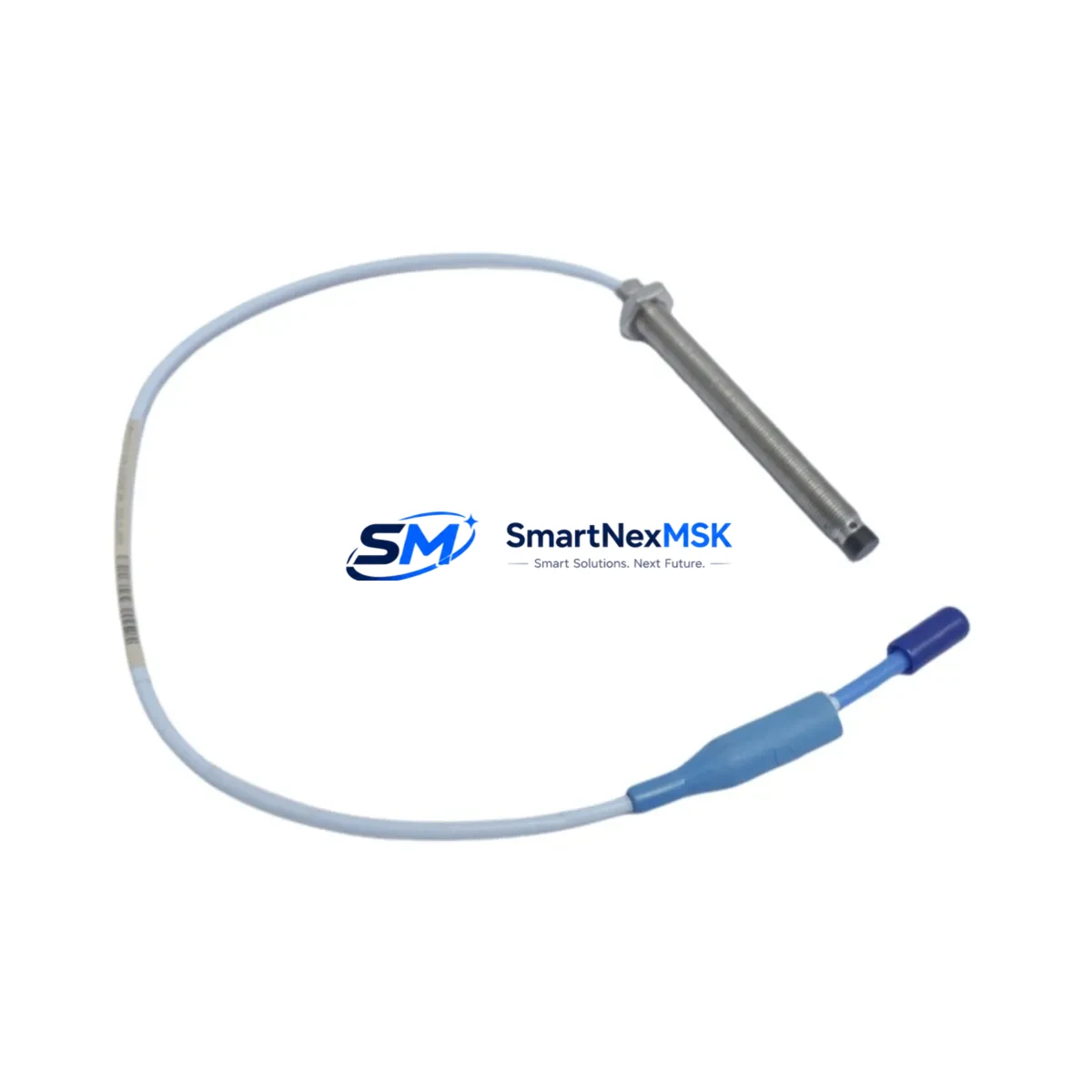
Bently Nevada 330103-00-10-05-02-00 3300 XL Retrofit-Ready Proximity Probe: Seamless Compatibility for Legacy System Upgrades
The Bently Nevada 330103-00-10-05-02-00 is a 10mm proximity probe with a 5-meter extension cable, designed for use within the 3300 XL Series continuous machinery monitoring platform. This probe is a direct retrofit replacement for aging or discontinued units in rotating machinery protection systems, including steam turbines, gas compressors, centrifugal pumps, and gearboxes. Whether you are restoring a failed monitoring loop, upgrading a legacy control cabinet, or migrating from an older 3300 Series rack to a current-generation 3300 XL system, this probe delivers the dimensional accuracy, signal linearity, and environmental robustness required for uninterrupted plant operations.
The 330103-00-10-05-02-00 operates as part of a complete proximity transducer system. It pairs directly with the 330130-080-00-00 extension cable and the 330180-X1-05 proximitor/seismic transducer to form a calibrated measurement chain. When retrofitting, engineers must verify that the existing proximitor module installed in the 3500/42M or 3300/16 monitor rack is compatible with the probe’s sensitivity factor (200 mV/mil or 7.87 V/mm). Mismatched sensitivity between the probe and the proximitor will cause incorrect gap voltage readings and may trigger false alarms or missed trips on the 3500 Series machinery protection system.
Upgrade Compatibility Table
| Parameter | 330103-00-10-05-02-00 (This Unit) | Notes / Retrofit Guidance |
|---|---|---|
| Probe Tip Diameter | 10 mm | Verify existing probe bore in bearing housing; no machining required for direct swap |
| Cable Length | 5 m (extension cable) | Match with 330130-080-00-00 or equivalent; total system cable must not exceed proximitor spec |
| Sensitivity | 200 mV/mil (7.87 V/mm) | Must match proximitor calibration; confirm on 3500/42M or 3300/16 channel card |
| Gap Voltage Range | −10 VDC to −18 VDC | Set gap to −10.0 VDC (1.0 mm) during commissioning; verify with 3500/94 calibrator |
| Supply Voltage | −24 VDC (nominal) | Confirm rack power supply capacity; 3500 rack PSU must support additional channel load |
| Connector Type | Standard BNC / coaxial | Compatible with existing 3300 XL and 3500 Series field wiring; no adapter required |
| Communication Protocol | Analog (4–20 mA / voltage output via proximitor) | Integrates with DCS via 3500/92 communication gateway or direct 4–20 mA to DCS AI card |
| Installation Standard | API 670 compliant | Meets machinery protection standard for radial vibration, axial position, and speed |
| Warranty | 12 Months | Covers manufacturing defects; includes pre-shipment functional test report |
Retrofit Planning for Existing Automation Systems
Successful integration of the 330103-00-10-05-02-00 into an existing monitoring architecture requires a structured pre-installation review. Begin by auditing the current rack configuration. In a typical 3500 Series chassis, the probe connects through a field terminal block on the 3500/42M four-channel monitor module. Confirm that the terminal block wiring (positive, negative, and shield) is intact and that the coaxial cable run from the junction box to the rack is free of damage or moisture ingress.
If the existing system uses an older 3300/16 dual-channel monitor, the retrofit may require replacing the monitor card with a 3500/42M to gain access to enhanced alarm setpoint management and Modbus RTU communication. In this scenario, the 3500/20 rack interface module and the 3500/22M transient data interface should also be evaluated for firmware compatibility with the plant’s existing System 1 condition monitoring software.
For plants running a distributed control system such as a Honeywell Experion PKS or an Emerson DeltaV, the 3500/92 communication gateway module provides the Modbus TCP or OPC DA bridge between the 3500 rack and the DCS historian. Verify that the gateway’s node address and baud rate settings are documented before removing the old probe, as these parameters are stored in the rack configuration and may need to be re-entered after a channel reset.
During the physical swap, record the existing gap voltage before disconnecting the old probe. This baseline reading, typically between −9.5 VDC and −10.5 VDC for a correctly installed 10mm probe, serves as the reference for post-installation verification. After seating the new 330103-00-10-05-02-00 and torquing the probe tip to the manufacturer’s specification, reconnect the 330130-080-00-00 extension cable and restore power to the channel. Use the 3500/94 field calibrator to confirm the gap voltage is within the acceptable window before releasing the machine for operation.
Plants that also operate 3300/55 temperature monitors or 3500/61 temperature monitor modules in the same cabinet should confirm that the addition of a new proximity channel does not exceed the rack’s total power budget. The 3500/15 power supply module is rated for a defined maximum load; adding channels without verifying headroom can cause intermittent resets across all installed monitor cards.
For I/O expansion projects where the plant is adding new measurement points alongside the probe retrofit, the 3500/40M proximitor I/O module provides additional channel capacity without requiring a new rack. This is particularly useful in compressor train upgrades where radial vibration, axial position, and keyphasor signals must all be routed through a single 3500 chassis to a common System 1 server.
Downtime Control During System Migration
Minimizing unplanned downtime during a proximity probe retrofit requires preparation that begins well before the maintenance window. The most effective approach is to pre-configure the replacement 330103-00-10-05-02-00 and its associated 330130-080-00-00 extension cable as a tested assembly, with the gap voltage verified on a bench fixture using the 3500/94 calibrator before the unit reaches the field. This eliminates the most common source of commissioning delay: discovering a wiring or sensitivity mismatch only after the machine has been taken offline.
During the outage, protect the existing program logic stored in the 3500/42M monitor by exporting the channel configuration from the 3500 Rack Configuration Software before any hardware is disturbed. This configuration file captures all alarm setpoints, transducer type assignments, and communication parameters. If the channel card must be replaced as part of the upgrade, the saved configuration can be reloaded in minutes, avoiding the need to re-enter setpoints manually from P&ID markups or historical commissioning records.
For plants where the proximity monitoring loop feeds a safety instrumented system, coordinate with the SIS engineer to place the relevant SIS input in bypass mode before disconnecting the probe. Confirm with the control room that the bypass is active and that the machine’s other protection channels remain in service. This preserves the overall protection architecture while the single channel is being serviced, avoiding a full machine trip during the swap.
After reinstalling the probe and restoring the channel, perform a bump test by gently deflecting the shaft and confirming that the 3500/42M channel responds with the expected vibration amplitude change. This functional check, combined with the gap voltage verification, provides the documented evidence required by most plant mechanical integrity programs before returning the machine to service. Total elapsed time for a prepared, single-channel probe swap on a 3500 rack is typically 45 to 90 minutes, including documentation.
Retrofit Support FAQ
Q1: Is the 330103-00-10-05-02-00 a direct drop-in replacement for earlier 3300 Series probes with the same tip diameter?
A: In most cases, yes. The 10mm tip diameter and standard coaxial connector are physically compatible with existing probe bores and junction box wiring. However, you must confirm that the proximitor module in your rack is calibrated for the 200 mV/mil sensitivity factor of this probe. If your existing proximitor was calibrated for a different sensitivity, the channel must be recalibrated or the proximitor replaced before the new probe is placed in service.
Q2: What commissioning steps are required after installing this probe in a 3500 Series rack?
A: After physical installation, restore power to the channel and measure the gap voltage at the proximitor output. The target gap for a 10mm probe is typically −10.0 VDC, corresponding to a 1.0 mm air gap between the probe tip and the shaft. Adjust the probe position axially until the gap voltage is within the rack’s configured OK limit window. Then verify that the channel’s vibration reading is within the expected baseline range for the machine at rest. Document all readings in the commissioning record before releasing the machine.
Q3: Can this probe be used with a Bently Nevada 3300/16 monitor, or is it limited to 3500 Series racks?
A: The 330103-00-10-05-02-00 is compatible with both 3300 XL and 3500 Series monitor racks, provided the proximitor module is matched to the probe’s sensitivity. The probe itself is a passive transducer; the monitor card and proximitor determine the system’s measurement range and alarm logic. If you are migrating from a 3300/16 to a 3500/42M as part of a broader system upgrade, the probe can be reused without modification.
Q4: What does the 12-month warranty cover, and is a test report included with shipment?
A: The 12-month warranty covers manufacturing defects in materials and workmanship from the date of shipment. Each unit undergoes a pre-shipment functional test to verify sensitivity, output linearity, and connector integrity. A test report is included with the shipment documentation. Warranty claims require the unit to be returned in its original packaging with the test report and a description of the observed fault. Field damage resulting from incorrect installation, overvoltage, or mechanical impact is not covered under the standard warranty terms.
© 2026 SMARTNEXMSK. All rights reserved.
Original Source: https://smartnexmsk.com
Contact: [email protected] | +86 18259474341



