
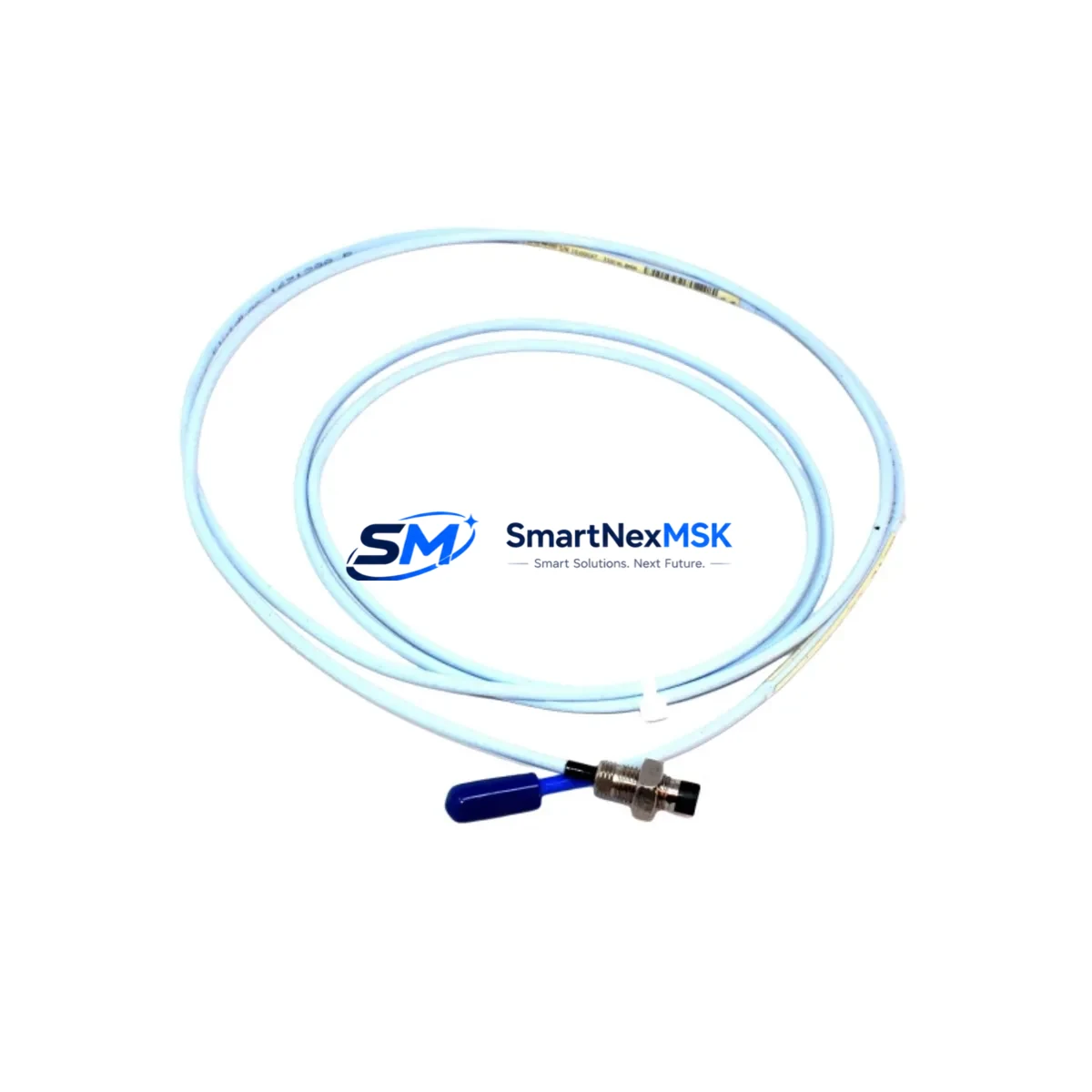
Bently Nevada 330103-06-25-10-02-00 Retrofit-Ready Proximity Probe for 3300 XL Control Systems
The Bently Nevada 330103-06-25-10-02-00 is an 8mm eddy-current proximity probe engineered for the 3300 XL Series vibration monitoring platform. Designed as a retrofit-ready replacement, this probe delivers a direct, drop-in upgrade path for aging or discontinued proximity measurement assemblies in rotating machinery protection systems. Whether you are replacing a failed probe in a gas turbine train, a steam turbine bearing housing, or a compressor shaft monitoring loop, the 330103-06-25-10-02-00 restores full system functionality with minimal engineering rework.
For facilities operating legacy 3300 Series or early-generation 3500 Series monitoring racks, this probe is a critical stocking item. Its 25 mm body length, 10 mm cable connector, and standard 2.0 m armored extension cable are dimensionally compatible with the majority of existing probe holder installations, reducing the need for mechanical modification during a planned or emergency replacement. The probe operates with the 3300 XL 8mm Proximitor Sensor (typically the 330180 series) and is fully compatible with the 3500/42M Proximitor/Seismic Monitor module when used within the validated probe-cable-Proximitor assembly.
Upgrade Compatibility Table
| Parameter | 330103-06-25-10-02-00 (This Unit) | Retrofit Notes |
|---|---|---|
| Probe Diameter | 8 mm | Matches standard 8mm probe holder bore; no machining required |
| Body Length | 25 mm | Verify gap setting (typically 1.0–1.5 mm) after installation |
| Cable Length | 2.0 m (extension cable) | Pair with 330130-080-00-00 or equivalent 8m extension for long runs |
| Compatible Proximitor | 330180 Series (3300 XL 8mm) | Do not mix with 5mm or 14mm Proximitor sensors |
| Monitor Compatibility | 3500/42M, 3300 XL Rack | Confirm I/O module slot assignment and channel address in rack configuration |
| Signal Output | –24 VDC bias, mV/mil linear range | Verify Proximitor power supply rail on 3500/20 Power Supply module |
| Installation Interface | Threaded probe holder, armored cable | Inspect probe holder threads and replace if worn |
| Communication Protocol | Analog (4–20 mA / voltage output via Proximitor) | Compatible with DCS analog input cards and existing historian tags |
| Replacement Recommendation | Replace as complete assembly (probe + cable + Proximitor) | Individual component replacement acceptable if others are within calibration |
| Commissioning Check | Gap voltage, OK relay, vibration baseline | Use Bently Nevada calibration fixture or field multimeter method |
| Warranty | 12-Month Warranty — covers manufacturing defects; includes pre-shipment functional test | |
Retrofit Planning for Existing Automation Systems
Integrating the 330103-06-25-10-02-00 into an existing machinery protection architecture requires a structured approach. Begin by auditing the current rack configuration in the 3300 XL or 3500 Series chassis. Identify the slot occupied by the 3500/42M Proximitor/Seismic Monitor and confirm that the channel assigned to the bearing being monitored is correctly mapped in the rack configuration software. If the plant is running an older 3300 Series rack without the XL upgrade, verify that the 8mm Proximitor sensor model installed is compatible with the probe’s output characteristics before proceeding.
Cable routing is a common source of delay during probe replacement. The 330103-06-25-10-02-00 ships with a 2.0 m integral cable; for installations where the Proximitor is mounted more than 2 m from the probe, a 330130-080-00-00 extension cable (8 m) is typically used to bridge the distance. Confirm that the total cable length does not exceed the validated assembly specification, as excessive cable capacitance will shift the linear range and affect gap calibration. All cable connections at the junction box should be inspected for corrosion, and the armored sheath should be checked for mechanical damage before the new probe is energized.
On the power supply side, the 3500/20 Power Supply module must be confirmed to be delivering a stable –24 VDC rail to the Proximitor. A degraded power supply is a frequent root cause of erratic OK relay behavior after probe replacement. If the plant is simultaneously upgrading the monitoring rack, consider replacing the 3500/20 alongside the probe assembly to eliminate this variable. For facilities migrating from a standalone 3300 Monitor to a full 3500 Series rack, the I/O terminal block wiring must be re-mapped to match the 3500 channel pinout — the signal, common, and OK relay terminals differ between generations.
HMI integration should be validated after probe installation. If the plant uses a System 1 Evolution condition monitoring platform or a third-party DCS historian, confirm that the analog input tag associated with this bearing channel is correctly scaled to the new probe’s sensitivity (typically 7.87 V/mm or 200 mV/mil). For plants using Modbus RTU or Ethernet/IP communication between the 3500 rack and the DCS, verify that the rack’s communication gateway — often a 3500/92 Communication Gateway — is correctly configured to pass the updated channel data without requiring a full rack restart. Where a TDI (Transient Data Interface) module such as the 3500/94 is installed, confirm that the transient capture settings are re-armed after the probe swap.
For plants with a Keyphasor reference signal (typically sourced from a 3500/25 Keyphasor Module), verify that the phase reference is stable and correctly assigned to the bearing channel being replaced. An unstable Keyphasor signal will produce erratic 1X and 2X vibration vectors in the monitoring system, which can mask the true mechanical condition of the machine after the retrofit.
Downtime Control During System Migration
Minimizing unplanned downtime during a proximity probe replacement requires pre-staging all components before the maintenance window opens. The 330103-06-25-10-02-00 should be bench-tested using a calibration target and a reference Proximitor before it is taken to the field. Confirm the gap voltage at the nominal installation gap (typically –10.0 VDC ± 0.5 VDC for an 8mm probe on a steel target) and document the result as part of the pre-installation test record.
To protect the original program logic during the migration, export the current rack configuration from the Rack Configuration Software (RCS) before any hardware changes are made. This configuration file contains all alarm setpoints, danger levels, channel assignments, and communication parameters. If the rack must be powered down for the probe swap, the DCS operator should place the affected channels in bypass mode to prevent spurious trips during the maintenance window. For critical machines that cannot be taken offline, a temporary portable vibration monitor can be used to maintain surveillance on the bearing while the permanent system is being serviced.
After the probe is installed and the gap is set, perform a full channel checkout: verify the OK relay status, confirm the vibration reading is within the expected baseline range, and check that the alarm and danger setpoints are active. Re-enable any bypassed channels in the DCS only after the channel checkout is complete and documented. Total planned downtime for a single probe replacement on a pre-staged system is typically 2–4 hours, including gap setting, cable dressing, and channel verification.
Retrofit Support FAQ
Q1: Is the 330103-06-25-10-02-00 a direct replacement for older 3300 Series proximity probes?
A: Yes, for installations using 8mm probe holders and the 3300 XL 8mm Proximitor sensor. If your existing installation uses a 5mm or 14mm probe, the probe holder bore and Proximitor model must be changed. Always verify the complete probe-cable-Proximitor assembly compatibility before ordering.
Q2: What wiring changes are required when replacing a 3300 probe with this unit in a 3500 rack?
A: The signal and common wiring from the Proximitor to the 3500/42M I/O module must be verified against the 3500 channel pinout. Terminal assignments differ from the 3300 Monitor. Refer to the 3500/42M Installation and Operation Manual (Bently Nevada document 129768-01) for the correct terminal mapping.
Q3: Can this probe be used with a DCS analog input card directly, without a 3500 rack?
A: The probe itself outputs a high-impedance signal that requires a Proximitor sensor (such as the 330180 series) to condition the signal to a usable –24 VDC bias output. The Proximitor’s output (typically 0–10 VDC or 4–20 mA via a signal conditioner) can then be connected to a standard DCS analog input card. Direct connection of the probe to a DCS input without a Proximitor is not supported.
Q4: What does the 12-month warranty cover, and is pre-shipment testing included?
A: Every 330103-06-25-10-02-00 unit undergoes a functional pre-shipment test confirming gap linearity, output voltage, and OK relay operation. The 12-month warranty covers manufacturing defects in materials and workmanship from the date of shipment. It does not cover damage resulting from incorrect installation, gap setting errors, or use outside the validated probe-cable-Proximitor assembly specification.
© 2026 SMARTNEXMSK. All rights reserved.
Original Source: https://smartnexmsk.com
Contact: [email protected] | +86 18259474341



