
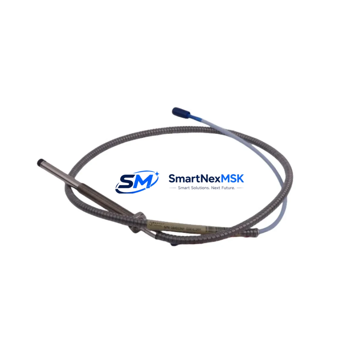
Bently Nevada 330104-00-22-10-02-CN 3300 XL Retrofit-Ready Proximity Probe: Compatible Modernization for Legacy Vibration Monitoring Systems
The Bently Nevada 330104-00-22-10-02-CN is a 3300 XL Series proximity probe designed for continuous shaft vibration and position monitoring in rotating machinery applications including turbines, compressors, pumps, and gearboxes. As legacy 3300 XL installations age and original spare parts become increasingly difficult to source, this unit serves as a verified retrofit-ready replacement that preserves existing wiring infrastructure, rack architecture, and signal conditioning compatibility — minimizing engineering rework and unplanned downtime during system modernization.
Whether you are replacing a failed probe in an operating plant, upgrading a decommissioned monitoring loop, or consolidating spare parts inventory ahead of a scheduled outage, the 330104-00-22-10-02-CN provides a direct-fit solution with documented compatibility across the 3300 XL platform. All units are pre-tested prior to shipment and covered by a 12-month warranty from date of delivery.
Upgrade Compatibility Table
| Parameter | Details |
|---|---|
| SKU / Part Number | 330104-00-22-10-02-CN |
| Series Compatibility | Bently Nevada 3300 XL Series |
| Probe Type | Eddy-Current Proximity Probe |
| Cable Length | 22 ft (6.7 m) integral cable |
| Tip Diameter | 10 mm |
| Thread | M10 x 1 (standard 3300 XL mounting) |
| Connector | 2-pin MIL-spec, compatible with 3300 XL extension cables |
| Signal Output | -18 VDC nominal, eddy-current linear range |
| Installation Requirement | Direct replacement — no bracket modification required |
| Communication / Protocol | Analog signal; compatible with 3300 XL Proximitor® sensor drivers |
| Replacement Recommendation | Replaces OEM 330104-00-22-10-02-CN; verify gap voltage after installation |
| Commissioning Notes | Re-gap to manufacturer spec (typically 1.0–2.0 mm); confirm OK LED on Proximitor® driver |
| Warranty | 12 months from date of shipment |
Retrofit Planning for Existing Automation Systems
Replacing a proximity probe in an active 3300 XL monitoring system requires careful coordination across multiple hardware layers. Before removing the failed 330104-00-22-10-02-CN, engineers should document the existing gap voltage reading at the associated Proximitor® sensor — typically a 3300 XL 8mm or 3300 XL 11mm Proximitor® driver module mounted in the 3300 XL rack. This baseline reading confirms the target air gap for the replacement probe and prevents misconfiguration during reinstallation.
The 3300 XL rack itself — whether a 4-slot, 8-slot, or 16-slot chassis — does not require modification for this probe swap. The extension cable connecting the probe to the Proximitor® driver, such as a 330130-series or 330140-series extension cable, should be inspected for continuity and connector integrity before reuse. If the extension cable shows signs of insulation damage or connector corrosion, replacement with a compatible 3300 XL extension cable is recommended to avoid signal noise that could trigger false alarms in the vibration monitoring loop.
At the rack level, the 3500/40M Proximitor®/Seismic Monitor or the 3300 XL Dual Proximitor® Monitor card should be verified for firmware revision compatibility. In systems where the monitoring rack interfaces with a DCS or safety system via a 3500 Rack Interface Module (RIM) or a Modbus/RS-485 gateway, no protocol reconfiguration is required — the analog signal chain from probe to Proximitor® driver to monitor card remains unchanged. However, if the plant is simultaneously migrating from a legacy 3300 XL rack to a newer 3500 Series rack, the probe’s signal characteristics must be re-validated against the 3500 Series Proximitor® sensor specifications, as gap voltage scales and sensitivity factors may differ.
For plants running GE Mark V, Mark VI, or Emerson Ovation DCS platforms that receive vibration data from the 3300 XL system via hardwired 4–20 mA or ±10 V analog outputs, the probe replacement is transparent to the DCS — no I/O card reconfiguration or controller logic changes are needed. Similarly, HMI screens displaying shaft vibration trends in systems such as GE iFIX, Wonderware InTouch, or Rockwell FactoryTalk do not require updates, as the signal path and engineering unit scaling remain identical after probe replacement.
In applications where the 330104-00-22-10-02-CN monitors axial position in addition to radial vibration — common in steam turbine and centrifugal compressor trains — the thrust position channel should be re-zeroed after probe installation using the plant’s established thrust calibration procedure. Coordinate with the control room operator to temporarily inhibit the associated trip and alarm outputs in the 3500 Series Safety Monitor or 3300 XL Dual Monitor card during the re-gapping and calibration window to prevent spurious shutdowns.
Downtime Control During System Migration
Minimizing production impact during a proximity probe replacement begins with pre-staging all required components before the maintenance window opens. Confirm that the replacement 330104-00-22-10-02-CN, the appropriate installation tool (typically a 3300 XL probe driver wrench), and a calibrated gap voltage meter are on-site and ready before isolating the monitoring channel.
In most 3300 XL installations, individual monitoring channels can be inhibited at the monitor card level without shutting down the entire rack. This allows the failed probe channel to be taken offline while adjacent channels — monitoring other bearing positions or axial thrust — continue to protect the machine. Confirm the inhibit status with the control room before proceeding, and document the inhibit in the plant’s permit-to-work system.
Once the replacement probe is installed and gapped, restore the channel inhibit and verify the gap voltage reading against the documented baseline. A reading within ±0.5 VDC of the original baseline confirms correct installation. Re-enable alarms and trips only after the gap voltage is stable and the OK output on the Proximitor® driver is confirmed active. The entire channel swap — from isolation to restoration — can typically be completed within a two-hour maintenance window when components are pre-staged and the calibration procedure is followed without deviation.
For plants with redundant monitoring architectures using dual-probe configurations on critical machinery, the replacement can often be performed online by switching the protection system to the redundant channel, replacing the failed probe, and then returning to normal dual-channel operation — eliminating the need for a machine shutdown entirely.
Retrofit Support FAQ
Q1: Is the 330104-00-22-10-02-CN a direct drop-in replacement for the original Bently Nevada part?
Yes. This unit is manufactured to the same dimensional and electrical specifications as the original 330104-00-22-10-02-CN. It uses the same M10 x 1 thread, 10 mm tip diameter, 22 ft cable length, and 2-pin MIL-spec connector, and is compatible with all standard 3300 XL Proximitor® sensor drivers without bracket modification or wiring changes.
Q2: What commissioning steps are required after installation?
After mechanical installation, set the probe gap to the manufacturer-specified air gap (typically 1.0–2.0 mm depending on target material) and verify the gap voltage at the Proximitor® driver output. Confirm the OK LED is active and the gap voltage is within the linear range specified on the Proximitor® driver label. For thrust position channels, re-zero the position reading per the plant calibration procedure before re-enabling trip outputs.
Q3: Can this probe be used with a 3500 Series rack if we are migrating from 3300 XL?
The 330104-00-22-10-02-CN probe is designed for use with 3300 XL Proximitor® sensor drivers. If migrating to a 3500 Series rack, verify that the 3500 Series Proximitor® sensor module (such as the 3500/42M) is configured for the same probe sensitivity and gap voltage range. In most cases, the probe itself is compatible, but the Proximitor® driver module and its configuration parameters must be validated against the 3500 Series documentation before enabling machine protection.
Q4: What does the 12-month warranty cover, and how is it claimed?
The 12-month warranty covers manufacturing defects and functional failures under normal operating conditions from the date of shipment. Units that fail within the warranty period will be replaced or repaired at no charge. To initiate a warranty claim, contact our sales team with the order number, installation date, and a description of the failure. All units undergo functional testing prior to shipment to minimize field failures.
© 2026 SMARTNEXMSK. All rights reserved.
Original Source: https://smartnexmsk.com
Contact: [email protected] | +86 18259474341



