
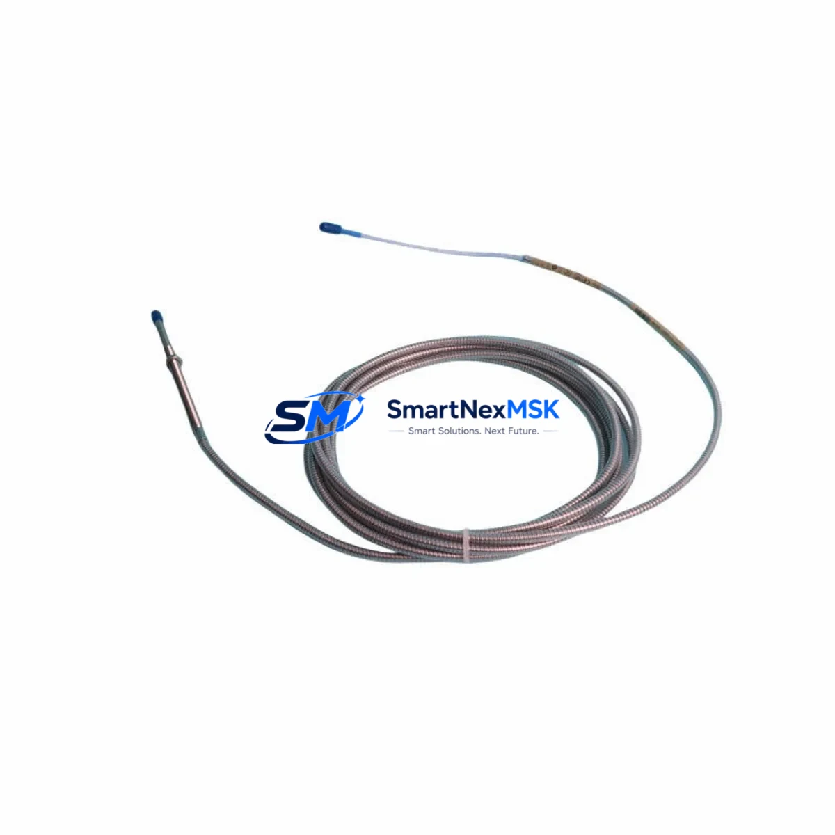
Bently Nevada 330104-06-16-50-02-00 3300 Series Spare: Precision Spare Parts for Industrial Downtime Control
The Bently Nevada 330104-06-16-50-02-00 is an original eddy current proximity probe engineered for the 3300 Series vibration monitoring system — one of the most widely deployed machinery protection platforms in rotating equipment applications worldwide. Whether you are managing a planned turnaround, responding to an unplanned trip, or building a strategic spare parts inventory for a critical compressor train or turbine skid, this probe is a direct, specification-matched replacement that restores system integrity without requiring recalibration of the entire monitoring loop.
Maintenance engineers working on gas turbines, centrifugal compressors, steam turbines, and large motor-driven pumps rely on the 3300 Series for continuous shaft displacement and vibration measurement. When a probe fails or degrades — whether due to cable damage, connector corrosion, or tip wear from proximity to the shaft — the entire channel goes offline, triggering a system alarm or a protective shutdown. Having a verified, tested spare on the shelf is the single most effective way to minimize mean time to repair (MTTR) and restore production within the maintenance window.
Spare Maintenance Table
| Parameter | Specification |
|---|---|
| Part Number | 330104-06-16-50-02-00 |
| Brand | Bently Nevada |
| Series | 3300 Series (3300 XL 8mm Proximity Transducer System) |
| Type | Eddy Current Proximity Probe |
| Probe Diameter | 8 mm |
| Cable Length | 6 ft (approx. 1.83 m) integral cable |
| Extension Cable Length | 16 ft (approx. 4.88 m) |
| Total System Length | 5.0 m (standard) |
| Output Sensitivity | 200 mV/mil (7.87 V/mm) |
| Operating Gap Range | 0.25 – 2.25 mm (10 – 90 mil) |
| Supply Voltage | −24 VDC (nominal) |
| Operating Temperature | −35°C to +177°C (probe tip) |
| Target Material Compatibility | AISI 4140 steel (standard); verify for non-ferrous shafts |
| Connector Type | MIL-C-5015 style (standard Bently Nevada) |
| Compatibility | 3300 Series monitors, 3500 Series (with verified driver pairing), Proximitor® 3300 XL |
| Application | Radial vibration, axial position, differential expansion, eccentricity |
| Installation Environment | Industrial — oil mist, high temperature, high vibration zones |
| Maintenance Recommendation | Replace probe and extension cable as a matched set; re-verify gap voltage after installation |
| Pre-shipment Testing | Electrically tested and verified before dispatch |
| Warranty | 12 Months |
| Origin | USA (Original Bently Nevada) |
Maintenance Planning for Continuous Operation
When replacing the 330104-06-16-50-02-00 proximity probe in the field, a disciplined maintenance engineer does not stop at the probe itself. The 3300 Series transducer system is a three-component chain — probe, extension cable, and Proximitor® sensor — and the performance of the entire channel depends on the integrity of each element. If the probe has failed due to cable damage or connector corrosion, the matched extension cable (such as the 330130-045-00-00 or equivalent 3300 Series extension) should be inspected and replaced simultaneously to avoid a repeat failure within the same maintenance interval.
The Proximitor® sensor — commonly the 3300 XL 8mm Proximitor® (e.g., 330180-X1-05) — should be checked for output voltage stability and correct gap voltage (typically −10 VDC at the nominal operating gap). A drifting Proximitor® output is a leading indicator of sensor degradation and can cause false vibration readings even with a new probe installed. While the cabinet is open, inspect the field wiring terminal blocks and verify that all signal cable shields are grounded at one end only, as ground loops are a common source of noise in proximity measurement circuits.
For installations where the 330104-06-16-50-02-00 feeds into a 3500 Series rack — particularly the 3500/42M Proximitor®/Seismic Monitor or the 3500/40M Proximitor® Monitor — confirm that the monitor channel is configured for the correct transducer type and sensitivity before returning the machine to service. The rack’s I/O module terminal assignments and the OK relay output should be verified against the original loop drawing. If the plant uses a Bently Nevada 3500/20 Power Supply module, check the −24 VDC rail voltage under load, as a sagging supply rail can cause intermittent probe OK dropouts that are difficult to diagnose without a calibrated reference.
In DCS-integrated plants where the proximity channel feeds a 4–20 mA signal conditioner or a signal isolator (such as a DIN-rail mounted galvanic isolator) before entering the DCS I/O card, the isolator’s input impedance and bandwidth should be confirmed compatible with the 3300 Series output. Replacing the probe without verifying the downstream signal path can result in a correctly functioning probe that still produces erroneous readings at the DCS historian. For older installations, consider upgrading aging signal isolators as part of the same work order to reduce future diagnostic complexity.
Maintenance planners building a comprehensive spare parts kit for a 3300 Series-equipped machine train should consider stocking the following alongside the 330104-06-16-50-02-00: a matched 3300 Series extension cable, a spare Proximitor® sensor, a set of MIL-spec connector backshells and contacts for field repair, spare terminal block inserts for the monitor rack, and a replacement 3500/20 power supply module if the rack is more than ten years old. For plants with multiple identical machines, a single spare rack card — such as the 3500/42M I/O module — can serve as a common spare across all units and significantly reduce the parts investment required for full redundancy coverage.
Site Replacement Workflow
Step 1 — Isolation and Permit: Obtain a work permit and isolate the monitor channel at the 3500 rack or 3300 monitor. Place the channel in bypass mode to prevent a spurious trip during probe removal. Document the existing gap voltage reading before disconnecting the probe.
Step 2 — Probe Removal: Disconnect the extension cable at the Proximitor® sensor. Unthread the probe from the probe holder, noting the number of turns to the original gap setting. Inspect the probe tip for physical damage and the cable jacket for cuts or abrasion.
Step 3 — New Probe Installation: Thread the 330104-06-16-50-02-00 replacement probe into the holder. Set the initial gap to the documented value (typically 1.0–1.5 mm for radial vibration applications). Reconnect the extension cable and Proximitor® sensor.
Step 4 — Gap Verification: With the monitor channel still in bypass, power the Proximitor® and measure the output voltage. Adjust the probe gap until the output matches the nominal value specified in the loop calibration record (typically −10.0 VDC ± 0.5 VDC at the operating gap). Fine-tune as required.
Step 5 — Channel Restoration: Remove the bypass, restore the channel to normal monitoring mode, and verify that the OK relay is energized and the vibration reading is within the expected baseline range. Log the as-left gap voltage and vibration reading in the maintenance management system.
This workflow is compatible with both direct replacement of legacy 3300 Series probes and cross-compatibility installations where the 330104-06-16-50-02-00 is used to replace an older 330104 variant with a different cable length configuration. The standardized sensitivity of 200 mV/mil ensures that no monitor reconfiguration is required when replacing within the same probe diameter family.
Spare Parts Support FAQ
Q1: Is the 330104-06-16-50-02-00 compatible with both 3300 and 3500 Series monitors?
The 330104-06-16-50-02-00 is natively designed for the 3300 XL 8mm Proximitor® system. It is also compatible with 3500 Series monitors (such as the 3500/42M) when used with the correct matched Proximitor® sensor and when the monitor channel is configured for 200 mV/mil sensitivity. Always verify the driver-probe pairing against the Bently Nevada system documentation before installation in a 3500 rack.
Q2: How is the probe tested before shipment?
Every 330104-06-16-50-02-00 unit is electrically tested prior to dispatch. Testing includes verification of coil resistance, insulation integrity, and output sensitivity against a calibrated target. A test report is available upon request. The 12-month warranty covers manufacturing defects and electrical performance under normal operating conditions.
Q3: Should the probe and extension cable always be replaced together?
Bently Nevada recommends treating the probe, extension cable, and Proximitor® sensor as a matched system. The total cable length (probe integral cable + extension cable) determines the system’s electrical characteristics and calibration. Mixing cable lengths from different configurations can shift the output sensitivity and introduce measurement error. When replacing the 330104-06-16-50-02-00, always verify that the extension cable length matches the original system design — in this case, a 16 ft (approx. 4.88 m) extension for a 5.0 m total system.
Q4: What is the recommended inventory strategy for critical rotating equipment?
For machines classified as critical (no installed spare, direct production impact), industry best practice is to maintain a minimum of one complete transducer set — probe, extension cable, and Proximitor® sensor — as a dedicated on-site spare. For plants with multiple identical machines, a pooled spare strategy with two complete sets per probe model is typically sufficient. Long lead times for original Bently Nevada parts make pre-stocking essential; sourcing through a verified distributor with tested inventory and a documented warranty policy eliminates the risk of receiving untested or counterfeit components during an emergency shutdown.
© 2026 SMARTNEXMSK. All rights reserved.
Original Source: https://smartnexmsk.com
Contact: [email protected] | +86 18259474341



