
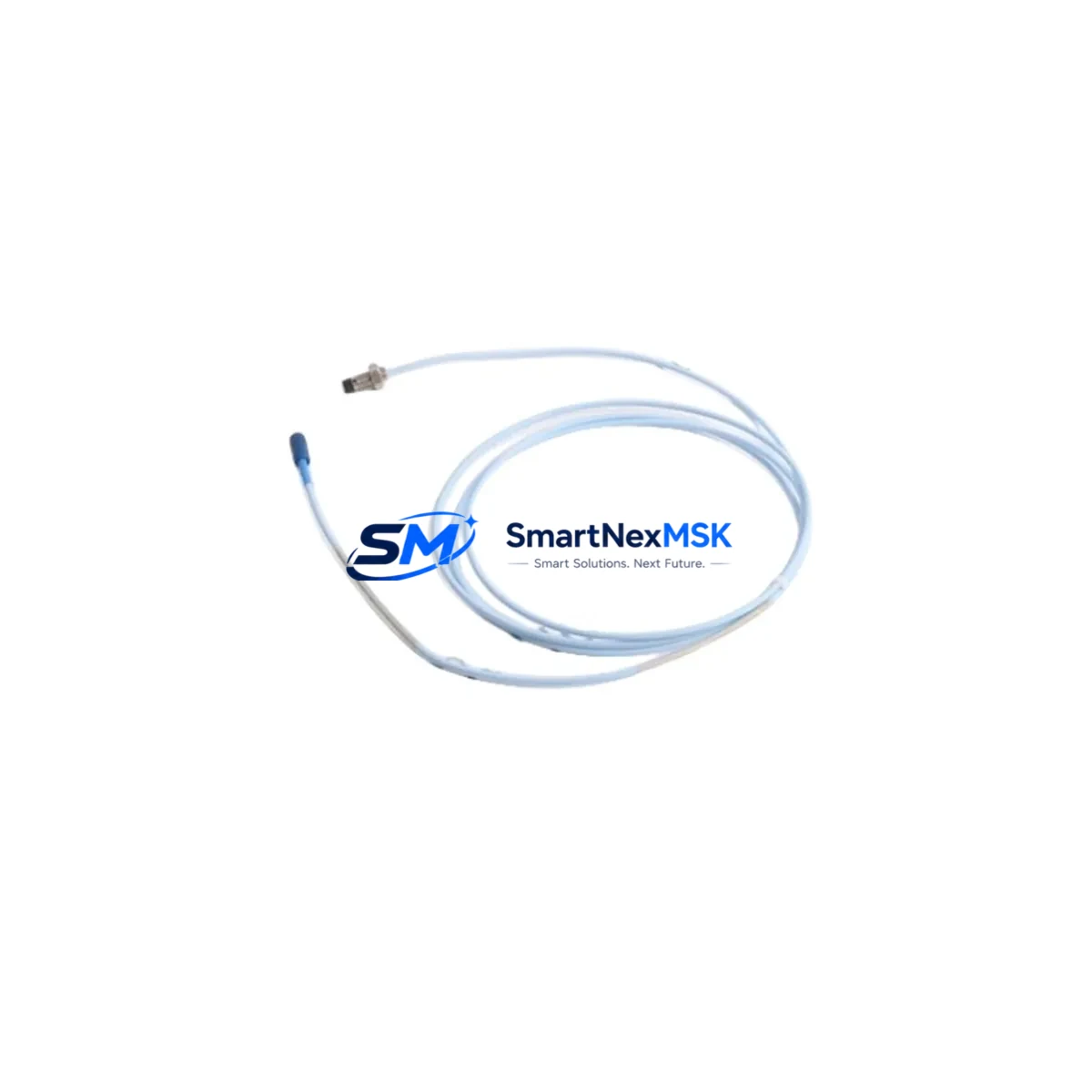
Bently Nevada 330104-07-12-10-02-CN Spare 3300 XL Automation: Spare Parts Replacement & Industrial Downtime Risk Control
The Bently Nevada 330104-07-12-10-02-CN is an original eddy current proximity sensor engineered for the 3300 XL Series continuous machinery monitoring system. Designed for critical rotating equipment — including turbines, compressors, pumps, and motors — this sensor delivers precise non-contact displacement and vibration measurement essential to plant-wide condition monitoring. When this component fails or degrades, the entire vibration monitoring loop is compromised, creating unplanned downtime risk and potential equipment damage. Maintaining a verified spare of the 330104-07-12-10-02-CN in your on-site inventory is a fundamental element of any proactive maintenance strategy.
This unit is sourced as an original spare, individually tested prior to shipment, and backed by a 12-month warranty. It is compatible with the Bently Nevada 3300 XL monitoring system architecture and is suitable for direct replacement in existing installations without system reconfiguration, provided cable length and gap voltage specifications are matched during commissioning.
Spare Maintenance Table
| Parameter | Specification |
|---|---|
| Part Number | 330104-07-12-10-02-CN |
| Brand | Bently Nevada |
| Series | 3300 XL |
| Product Type | Eddy Current Proximity Sensor |
| Measurement Type | Non-contact displacement / vibration |
| Cable Length | 7.62 m (25 ft) — per SKU suffix |
| Thread Size | M12 x 1 (standard probe body) |
| Output Signal | DC voltage proportional to gap distance |
| Operating Temperature | -35°C to +120°C (probe tip) |
| Target Material Compatibility | Steel, stainless steel, iron alloys |
| System Compatibility | Bently Nevada 3300 XL Monitor Series |
| Installation | Direct replacement; gap voltage re-verification required |
| Origin | CN |
| Condition | Original spare, pre-shipment tested |
| Warranty | 12 months from date of shipment |
| Application Environment | Heavy industry: turbines, compressors, pumps, motors |
| Maintenance Recommendation | Inspect gap voltage and cable integrity every 6–12 months; replace on signal drift >5% |
Maintenance Planning for Continuous Operation
When a 330104-07-12-10-02-CN proximity sensor is flagged for replacement during a planned outage or emergency shutdown, experienced maintenance engineers know that the sensor itself is rarely the only component requiring attention. A thorough inspection of the full vibration monitoring loop and surrounding control cabinet is essential to prevent repeat failures and ensure system integrity after restart.
Begin by verifying the condition of the 3300 XL proximitor/driver module (such as the 3300/16 or 3300/20 series), which conditions the sensor signal before it reaches the monitor. A degraded proximitor can cause false readings even with a new probe installed. Next, inspect the extension cable — typically a 330130-series armored cable — for insulation damage, connector corrosion, or continuity loss, as cable faults are a leading cause of proximity system failures in high-vibration environments.
Check the 3300 XL monitor rack and its associated power supply module (e.g., 3300/15 or equivalent) for stable output voltage. Voltage fluctuations at the power supply directly affect sensor gap voltage calibration and can introduce measurement error. If the control cabinet houses a Bently Nevada 3500 Series rack alongside the 3300 XL system, verify that the 3500/15 power supply and 3500/42M position monitor cards are also within specification, as cross-system power rail issues are common in aging installations.
For installations where the proximity sensor feeds into a DCS or PLC I/O card, confirm that the analog input module receiving the 0–24 VDC proximity signal is functioning correctly and that signal scaling parameters have not drifted. In Yokogawa, Emerson, or Honeywell DCS environments, this often means verifying the AI card’s input range configuration and checking for ground loop issues using a signal isolator or galvanic isolation barrier in the signal path.
Do not overlook the terminal blocks and field wiring within the junction box. Loose terminations, oxidized contacts, and undersized wire gauge are frequent contributors to intermittent proximity faults. Inspect and torque all terminals, and replace any corroded DIN rail terminal blocks as part of the same maintenance window. If the system uses Zener barriers or intrinsic safety isolators for hazardous area compliance, verify their integrity and replace any units showing increased resistance or leakage current.
Finally, if the plant operates an HMI or operator workstation connected to the 3300 XL system via serial or Ethernet, confirm that the communication link is stable and that alarm setpoints for radial vibration, axial position, and gap voltage are correctly configured following sensor replacement. Documenting the as-found and as-left gap voltage readings in the CMMS ensures traceability and supports future predictive maintenance decisions.
Site Replacement Workflow
Replacing the 330104-07-12-10-02-CN in the field follows a structured sequence to minimize downtime and ensure measurement accuracy is restored before the machine is returned to service.
Step 1 — Isolation & Lockout: De-energize the proximitor/driver and isolate the sensor circuit per site LOTO procedures. Record the existing gap voltage and vibration baseline from the DCS historian or local monitor display before disconnection.
Step 2 — Physical Removal: Disconnect the extension cable at the proximitor end. Unthread the probe from the mounting bracket, noting the installed gap distance (typically 1.0–2.5 mm for steel targets). Inspect the probe tip and target surface for wear, scoring, or contamination.
Step 3 — New Sensor Installation: Thread the replacement 330104-07-12-10-02-CN into the bracket to the same approximate gap distance. Reconnect the extension cable, ensuring connector seating is secure and the cable is routed away from heat sources and mechanical contact points.
Step 4 — Gap Voltage Verification: Energize the proximitor and measure the DC output voltage at the monitor input. Adjust the probe gap until the output falls within the linear range specified in the 3300 XL system documentation (typically -10 VDC ± 1 V at nominal gap). Lock the probe position with the jam nut.
Step 5 — Functional Test & Return to Service: Confirm alarm and danger setpoints are active on the monitor. Verify the DCS is receiving a valid signal within the expected engineering unit range. Document as-left gap voltage, cable continuity test results, and sensor serial number in the maintenance record before releasing the machine for restart.
This workflow is applicable to both planned turnaround replacements and emergency swap-outs, and is designed to restore full monitoring capability with minimal impact on production schedules.
Spare Parts Support FAQ
Q1: Is the 330104-07-12-10-02-CN a direct drop-in replacement for older 330104 series probes?
A: The 330104-07-12-10-02-CN is part of the Bently Nevada 330104 proximity probe family and is designed for use with 3300 XL proximitor/driver modules. Compatibility with earlier 3300 series (non-XL) systems should be verified against the proximitor model number and system documentation, as connector types and cable impedance specifications may differ. We recommend confirming the proximitor model before ordering.
Q2: What is included in the 12-month warranty, and what does pre-shipment testing cover?
A: Each unit undergoes electrical continuity verification, output linearity check, and physical inspection before dispatch. The 12-month warranty covers manufacturing defects and functional failure under normal operating conditions. It does not cover damage resulting from incorrect installation, overvoltage, or mechanical impact. Warranty claims are supported with return authorization and replacement dispatch within agreed lead times.
Q3: How should this spare be stored if not immediately installed?
A: Store the 330104-07-12-10-02-CN in its original packaging in a dry, temperature-controlled environment (5°C–40°C), away from strong magnetic fields and corrosive atmospheres. The probe tip and connector should remain capped until installation. Shelf life under proper storage conditions is typically 3–5 years without performance degradation. Inspect the cable jacket and connector contacts before installation if stored for more than 12 months.
Q4: Can you supply multiple units for a plant-wide spare parts inventory program?
A: Yes. We support bulk procurement for planned maintenance programs, turnaround projects, and strategic spare parts inventory builds. Long-term supply agreements with fixed pricing and reserved stock allocation are available for facilities operating multiple 3300 XL monitoring systems. Contact our team to discuss quantity pricing, lead times, and consignment stocking options.
© 2026 SMARTNEXMSK. All rights reserved.
Original Source: https://smartnexmsk.com
Contact: [email protected] | +86 18259474341



