
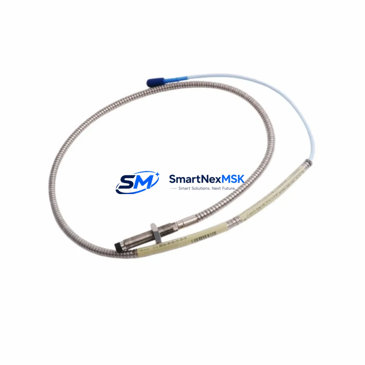
Bently Nevada 330104-10-20-10-02-05 Retrofit-Ready Proximity Probe for 3300 XL Control Systems
The Bently Nevada 330104-10-20-10-02-05 is a high-precision eddy-current proximity probe engineered for the 3300 XL Series vibration monitoring platform. As legacy rotating machinery protection systems reach end-of-service milestones, this probe serves as the primary retrofit solution for facilities migrating from discontinued 3300 Series configurations or upgrading aging condition monitoring infrastructure. With a 5 mm tip diameter, 10 mm linear range, and a standard 5-metre extension cable, the 330104-10-20-10-02-05 integrates directly into existing 3300 XL monitor racks without requiring mechanical re-engineering of the machine casing or bearing housing.
For plants operating legacy Bently Nevada 3300 NSv monitors or earlier 7200 Series proximity systems, the 330104-10-20-10-02-05 provides a validated upgrade path. The probe is fully compatible with the 3300 XL 8mm Proximitor® sensor (330180-X1-CN) and the standard 3300 XL extension cable assemblies. When replacing probes in a multi-channel rack, engineers should verify that the companion Proximitor® module firmware version supports the probe’s sensitivity specification of 7.87 V/mm (200 mV/mil) to avoid calibration drift on the 3500/42M Proximitor® Monitor or the 3500/40M Proximitor®/Seismic Monitor.
Before committing to a retrofit, the following compatibility checkpoints are essential: confirm the existing conduit and junction box accommodate the probe’s 5 mm body diameter and M8 thread; verify that the extension cable connector type matches the installed 330130-045-00-00 or equivalent cable assembly; and ensure the Proximitor® power supply rail within the 3500 rack delivers the required −24 VDC ±1 VDC. If the plant is running a 3300 rack with a 3300/16 I/O module, a rack migration to the 3500 Series backplane may be required, which in turn necessitates re-addressing module slots and updating the System 1 configuration database.
Upgrade Compatibility Table
| Parameter | Detail |
|---|---|
| SKU / Part Number | 330104-10-20-10-02-05 |
| Compatible Platform | Bently Nevada 3300 XL Series |
| Replaces / Upgrades | 3300 NSv, 7200 Series proximity probes |
| Probe Tip Diameter | 5 mm |
| Linear Range | 10 mm (0.4 in) |
| Sensitivity | 7.87 V/mm (200 mV/mil) |
| Cable Length | 5 m (standard) |
| Thread | M8 × 1.0 |
| Supply Voltage | −24 VDC ±1 VDC |
| Communication Compatibility | System 1 Evolution, 3500 Rack, 3300 XL Monitor |
| Installation Requirement | Direct drop-in for 3300 XL; rack migration may apply for 3300 NSv |
| Commissioning Note | Verify gap voltage (−10 VDC nominal) and re-zero in System 1 after installation |
| Warranty | 12 Months from date of shipment |
Retrofit Planning for Existing Automation Systems
A successful retrofit of the 330104-10-20-10-02-05 into an operating plant begins well before the maintenance window opens. The project scope typically involves auditing the existing 3300 XL monitor rack, identifying whether the installed 3300/20 Dual Voting Logic module or 3300/25 Keyphasor® module will remain in service, and confirming that the 3500/22M Transient Data Interface has sufficient channel capacity for the new probe signals. In turbine and compressor applications, the probe is commonly installed alongside a 330500-02-05 Velomitor® CT sensor for combined radial vibration and velocity measurement, providing redundant protection layers during the transition period.
Wiring adaptation is a frequent challenge. The 330104-10-20-10-02-05 uses a standard coaxial signal path through the 330130 extension cable to the Proximitor® sensor. If the existing conduit was routed for an older 7200 Series cable with a different connector pitch, a 330130-045-00-00 adapter cable or a custom junction box may be required. Terminal block assignments in the 3500 rack I/O module must be updated in the rack configuration software, and the 3500/01 Rack Interface Module should be placed in configuration mode before any wiring changes are made to prevent spurious trip signals from reaching the DCS or safety PLC.
For facilities running a Rockwell Automation ControlLogix or Allen-Bradley PLC alongside the Bently Nevada monitoring rack, the System 1 OPC-DA or OPC-UA data bridge must be reconfigured to reflect the new channel tag names after the probe swap. HMI screens built on FactoryTalk View or Wonderware InTouch that display bearing vibration trends will require tag remapping to maintain historical data continuity. Similarly, if the plant uses a Modbus RTU link between the 3500 rack and a SCADA gateway, the register map should be reviewed to confirm that the new probe’s channel address does not conflict with existing I/O allocations.
Downtime Control During System Migration
Minimizing unplanned downtime is the primary operational constraint in any proximity probe retrofit. The recommended approach is to pre-stage the 330104-10-20-10-02-05 probe, the companion 330180 Proximitor® sensor, and the 330130 extension cable as a matched, pre-tested assembly before the maintenance window. Gap voltage should be set on the bench using a calibrated gap simulator, targeting −10.0 VDC ±0.5 VDC at the nominal 1.0 mm installation gap, so that field commissioning is reduced to a final verification rather than a full calibration cycle.
During the cutover, the 3500 rack should be placed in bypass mode for the affected channels using the rack’s front-panel keyswitch or the System 1 software bypass command. This prevents the monitor from issuing a spurious trip to the turbine protection relay or the emergency shutdown system while the probe is being physically replaced. Original program logic in the safety PLC — whether it is a Triconex TRICON, a Honeywell Safety Manager, or a Siemens S7-400 FH — should be exported and archived before any rack configuration changes are committed, ensuring a clean rollback path if the commissioning reveals an unexpected compatibility issue.
After installation, the gap voltage reading should be confirmed at the Proximitor® output terminals, the System 1 trend display should show a stable DC gap signal, and a slow-roll vibration check at machine startup should confirm that the probe’s dynamic response is within the alarm setpoints defined in the 3500/42M monitor configuration. Full documentation of the as-found and as-left gap voltages, along with the updated rack configuration file, should be archived in the plant’s CMMS before the maintenance work order is closed.
Retrofit Support FAQ
Q1: Is the 330104-10-20-10-02-05 a direct replacement for the 330104-10-20-10-02-00?
Yes. The -05 suffix denotes the 5-metre cable length variant. The probe body, thread, tip diameter, sensitivity, and Proximitor® compatibility are identical to the -00 (no cable) and other cable-length variants. No changes to the monitor configuration or alarm setpoints are required when substituting cable-length variants within the 330104 family.
Q2: What commissioning steps are required after installation?
After physical installation, set the probe gap to achieve a Proximitor® output of −10.0 VDC ±0.5 VDC. Confirm the reading at the 3500 rack I/O terminal. In System 1, clear any latched alerts, verify the channel is no longer in bypass, and perform a slow-roll check to confirm dynamic signal quality. Update the rack configuration archive and record as-left gap voltage in the maintenance log.
Q3: Can this probe be used with a 3300 NSv monitor without a rack upgrade?
The 330104-10-20-10-02-05 is optimized for the 3300 XL platform. While the physical probe body may fit the same machine bore, the 3300 NSv monitor’s input conditioning and alarm logic are calibrated for the NSv Proximitor® sensor. A rack migration to the 3300 XL or 3500 Series is strongly recommended to ensure full specification compliance and to maintain warranty coverage.
Q4: What does the 12-month warranty cover?
The 12-month warranty covers manufacturing defects in materials and workmanship from the date of shipment. Each unit undergoes pre-shipment functional testing including gap voltage verification, insulation resistance check, and cable continuity test. Warranty claims are supported with a full test report. Units damaged by incorrect installation gap, reverse polarity supply voltage, or mechanical impact are not covered under the standard warranty terms.
© 2026 SMARTNEXMSK. All rights reserved.
Original Source: https://smartnexmsk.com
Contact: [email protected] | +86 18259474341



