
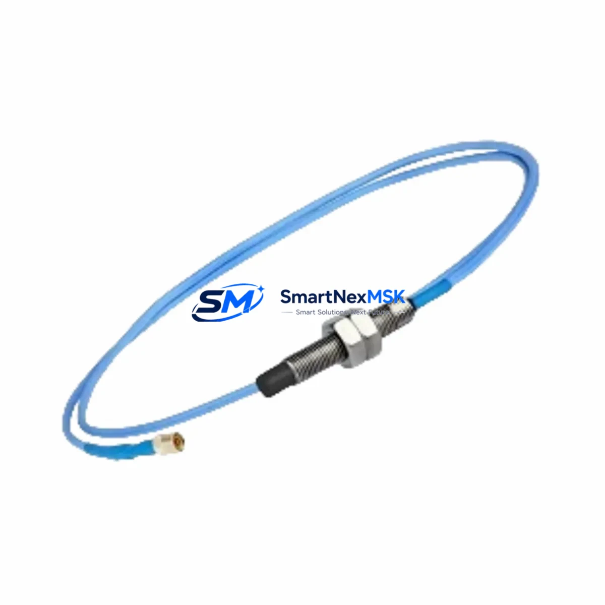
Bently Nevada 330105-02-12-05-12-05 Retrofit-Ready Proximity Probe for 3300 XL Control Systems
The Bently Nevada 330105-02-12-05-12-05 is a high-precision eddy-current proximity probe engineered for seamless integration into legacy and active Bently Nevada 3300 XL Series vibration monitoring systems. As original OEM units reach end-of-life or become increasingly difficult to source, this retrofit-ready replacement provides a verified drop-in solution for rotating machinery protection panels, turbine monitoring cabinets, and compressor control systems operating on the 3300 XL platform.
Whether you are executing a planned outage upgrade, responding to an unplanned probe failure, or modernizing an aging control cabinet, the 330105-02-12-05-12-05 delivers the electrical and mechanical compatibility required to restore system integrity without rewriting existing monitor configurations or recalibrating gap voltage setpoints.
Upgrade Compatibility Table
| Parameter | Detail |
|---|---|
| SKU / Part Number | 330105-02-12-05-12-05 |
| Compatible Series | Bently Nevada 3300 XL Vibration Monitoring System |
| Probe Type | Eddy-Current Proximity Probe |
| Cable Length | 2 m (probe) + 5 m (extension) — verify against existing conduit routing |
| Tip Diameter | 5 mm standard — confirm target material and gap range |
| Connector Interface | 3-pin MIL-spec — matches 3300 XL driver/monitor input terminals |
| Communication Compatibility | Analog 4–20 mA / voltage output; compatible with 3300 XL monitor cards |
| Installation Requirement | Verify bracket thread pitch, probe holder, and target gap (typically 1.0–2.0 mm) |
| Replacement Recommendation | Direct replacement for discontinued 330105 series probes in 3300 XL panels |
| Commissioning Note | Re-verify gap voltage at monitor card after installation; adjust if outside –10 VDC nominal |
| Warranty | 12 Months from date of shipment |
Retrofit Planning for Existing Automation Systems
Successful integration of the 330105-02-12-05-12-05 into an existing 3300 XL panel begins with a thorough pre-outage audit. Engineers should document the current probe gap voltage readings from the 3300 XL monitor card — typically a 3300/16 or 3300/20 series monitor — and record the OK relay status before disconnecting the original probe. This baseline ensures that post-installation commissioning can confirm restored functionality against known-good reference values.
The extension cable routing must be inspected for conduit integrity. In many legacy installations, the original 330130 series extension cable may show insulation degradation after years of exposure to heat, vibration, and process fluids. Replacing the probe without inspecting the extension cable is a common cause of post-retrofit signal anomalies. Similarly, the 330180 series proximitor/oscillator driver should be tested for output linearity before assuming the new probe is the sole source of any pre-existing alarm condition.
For panels that also house 3500 Series rack-based monitoring systems in adjacent bays, confirm that the 3300 XL wiring does not share common ground paths that could introduce noise into the new probe circuit. If the control cabinet includes a Bently Nevada 3300/55 dual-channel monitor or a 3300/25 radial vibration monitor, verify that channel-to-channel isolation is maintained after the probe swap.
Backplane and rack integrity should also be assessed. In older installations, the 3300 XL rack may have corroded DIN rail mounting points or loose terminal block connections on the 3300/10 power supply module. Addressing these mechanical issues during the same outage window prevents repeat interventions. If the system communicates vibration data upstream to a DCS or SCADA platform via a System 1 Evolution data gateway, confirm that the probe channel mapping in the gateway configuration matches the physical slot assignment after reinstallation.
Where HMI faceplate displays are tied to specific probe channel tags, coordinate with the control room operator to verify that the HMI alarm setpoints and trend historian tags remain correctly mapped after the probe replacement. In some legacy DCS integrations, a probe channel reassignment can inadvertently orphan a historian tag, causing data gaps in the vibration trend record.
Downtime Control During System Migration
Minimizing unplanned downtime during a proximity probe replacement on a live 3300 XL system requires a structured hot-swap protocol. Where the process permits a brief bypass, use the monitor card’s inhibit function to suppress the OK relay trip output before disconnecting the probe. This prevents a nuisance trip to the machinery protection system while the probe is open-circuit during the swap.
Pre-stage the replacement 330105-02-12-05-12-05 probe alongside the correct extension cable and a calibrated gap-setting tool before the outage window opens. Confirm the target shaft material (typically 4140 steel or equivalent) and verify that the new probe’s sensitivity curve matches the monitor card’s configured scale factor — standard is 200 mV/mil (7.87 V/mm). Any deviation requires a scale factor adjustment at the monitor card, not a probe substitution.
Once the new probe is installed and the gap is set, restore the monitor card from inhibit and observe the OK LED and gap voltage simultaneously. A stable reading within the –10 VDC ±10% window confirms correct installation. Log the as-left gap voltage in the maintenance record and update the equipment history in the CMMS before closing the work order. This documentation protects the 12-month warranty claim and provides traceability for future audits.
For systems where a full outage is not feasible, consult with the machinery protection engineer about implementing a temporary portable vibration monitor on the shaft during the probe swap interval to maintain continuous protection coverage.
Retrofit Support FAQ
Q1: Is the 330105-02-12-05-12-05 a direct replacement for the original Bently Nevada probe in my 3300 XL panel?
Yes. The 330105-02-12-05-12-05 is designed as a drop-in replacement for the original 330105 series proximity probes used in 3300 XL vibration monitoring systems. Electrical characteristics, connector pinout, and sensitivity specifications are matched to the original OEM design. No monitor card reconfiguration is required in standard installations.
Q2: What commissioning checks are required after installation?
After mechanical installation, verify the probe gap voltage at the monitor card input (target: –10 VDC ±10% for standard steel targets). Confirm the OK relay energizes and that the vibration channel reads within the expected baseline range. If the system feeds a System 1 or DCS historian, verify that the channel tag is actively logging before closing the work order.
Q3: Can I reuse the existing extension cable and proximitor driver?
In most cases, yes — provided the existing 330130 extension cable and 330180 proximitor driver are within specification. Inspect the extension cable for insulation damage and test the driver output linearity before reuse. A degraded driver or cable will produce erratic gap voltage readings even with a new probe installed.
Q4: What does the 12-month warranty cover, and how is it claimed?
The 12-month warranty covers manufacturing defects and electrical performance failures under normal operating conditions from the date of shipment. Each unit undergoes pre-shipment functional testing. To initiate a warranty claim, contact [email protected] with the order reference, installation date, and a description of the fault condition. Replacement or credit will be processed upon evaluation.
© 2026 SMARTNEXMSK. All rights reserved.
Original Source: https://smartnexmsk.com
Contact: [email protected] | +86 18259474341



