
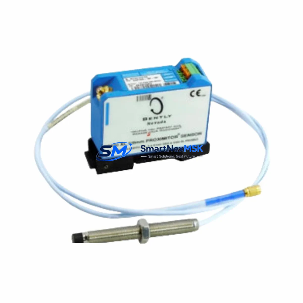
Bently Nevada 330105-02-12-10-12-05 Retrofit-Ready Proximity Probe for 3300 XL Control Systems
The Bently Nevada 330105-02-12-10-12-05 is a reverse-mount eddy-current proximity probe engineered for seamless integration into legacy and active 3300 XL Series vibration monitoring systems. As aging 3300 Series installations approach end-of-support milestones, plant engineers and reliability teams increasingly rely on this model as a direct retrofit solution — preserving existing wiring infrastructure, maintaining signal chain integrity, and eliminating the need for full-system overhauls. Whether you are replacing a failed probe on a critical rotating machine or executing a planned upgrade across multiple measurement points, the 330105-02-12-10-12-05 delivers the dimensional accuracy, cable length, and sensitivity specifications required for drop-in compatibility.
This probe is rated for a 5 mm nominal gap range and operates within the standard Bently Nevada -24 VDC proximitor supply voltage. Its 12-inch (305 mm) probe body length and 10-foot (3 m) integral cable are factory-matched to the 330130 series extension cables and the 3300 XL 8mm Proximitor® Sensor, ensuring that no recalibration of the signal conditioning chain is required when replacing a like-for-like unit. Engineers migrating from earlier 330100 or 330103 series probes will find that the 330105-02-12-10-12-05 maintains backward-compatible output sensitivity of 200 mV/mil (7.87 V/mm), allowing existing Bently Nevada 3500/40M Proximitor Monitor rack cards to accept the signal without firmware changes or channel rescaling.
Upgrade Compatibility Table
| Parameter | 330105-02-12-10-12-05 (This Unit) | Typical Legacy Probe (330100/330103) | Retrofit Notes |
|---|---|---|---|
| Probe Body Length | 12 in (305 mm) | 8–12 in (varies) | Confirm mounting boss depth before installation |
| Integral Cable Length | 10 ft (3 m) | 5–10 ft (varies) | Match to existing 330130 extension cable routing |
| Output Sensitivity | 200 mV/mil (7.87 V/mm) | 200 mV/mil | No monitor rescaling required |
| Supply Voltage | -24 VDC (from Proximitor) | -24 VDC | Verify Proximitor power rail before hot-swap |
| Thread Size | M10 × 1 mm | M10 × 1 mm | Direct thread-in replacement; check locknut torque spec |
| Communication / Protocol | Analog (4–20 mA / voltage) | Analog | Compatible with 3500 Series rack and TDXnet gateway |
| Installation Interface | 3300 XL Proximitor® Sensor | 3300 XL / 3300 NSv | Confirm Proximitor model: 330130 or 330180 |
| Replacement Recommendation | Direct drop-in for 330105 family | Cross-reference 330100, 330103 | Update probe serial in System 1 asset database |
| Commissioning Focus | Gap voltage, OK relay, trend baseline | Same | Log pre/post gap voltage; compare vibration baseline |
| Warranty | 12-Month Warranty — covers manufacturing defects and signal performance | Warranty void if probe tip is machined or modified | |
Retrofit Planning for Existing Automation Systems
A successful retrofit of the 330105-02-12-10-12-05 begins well before the maintenance window opens. The first step is a full audit of the existing probe installation: record the current gap voltage (typically -10 VDC ±0.5 V at nominal gap), document the 330130 Series extension cable routing and connector condition, and verify that the 3300 XL Proximitor® Sensor — whether a 330130-080-00-05 or a 330180 NSv variant — is within its own service life. If the Proximitor shows drift or intermittent OK relay behavior, plan to replace it alongside the probe rather than troubleshooting the new probe against a suspect conditioner.
For installations integrated into a Bently Nevada 3500 Series rack, confirm that the 3500/40M Proximitor Monitor card firmware is current and that the channel configuration in the rack’s System 1 software reflects the correct probe type and gap range. If the plant uses a TDXnet communication gateway to bridge the 3500 rack to a DCS or SCADA platform — such as a Honeywell Experion PKS or an Emerson DeltaV system — verify that the Modbus or OPC-DA tag mapping for the affected channel remains intact after the probe swap. A probe replacement should never require a DCS tag rebuild, but a gap voltage shift of more than 0.5 V post-installation is a reliable indicator that the extension cable or Proximitor needs attention before the machine is returned to service.
In multi-point installations — for example, a turbine train with X-Y proximity probe pairs on each bearing journal — replace probes in matched pairs where possible. Mismatched sensitivity between the X and Y channels on a single bearing can introduce apparent orbital distortion in the System 1 vibration display that does not reflect actual shaft motion. If only one probe in a pair is being replaced, perform a slow-roll vector check at less than 600 RPM to confirm that the new probe’s slow-roll compensation vector aligns with the historical baseline stored in the 3500/40M card.
Wiring adaptation is rarely required for a like-for-like 330105 family replacement, but engineers retrofitting from a 330100 or 330103 probe with a non-standard cable assembly should verify terminal block assignments at the 3500 rack I/O module. The standard Bently Nevada wiring convention assigns the probe center conductor to the COM terminal and the shield to the –24 VDC return, but some older field installations deviate from this convention. A wiring diagram review against the original commissioning package — or a continuity check with the Proximitor disconnected — takes less than ten minutes and eliminates the most common source of post-installation OK relay faults.
Downtime Control During System Migration
Minimizing unplanned downtime during a proximity probe replacement requires a structured pre-outage checklist and a clear rollback plan. Before the machine is taken offline, export the current vibration trend data and alert setpoints from System 1 or the 3500 rack configuration software. This snapshot serves as the acceptance baseline: after the new 330105-02-12-10-12-05 is installed and gapped, the post-installation slow-roll vibration amplitude and phase should fall within ±10% of the pre-outage baseline at the same speed reference point.
For critical machines where even a brief loss of vibration monitoring is unacceptable, consider using a Bently Nevada portable Commtest VB Series data collector or a handheld gap meter to maintain continuous observation of the adjacent bearing channels while the target channel is offline. If the plant’s safety instrumented system (SIS) relies on the 3500 rack’s OK relay output for a machine trip permissive, coordinate with the SIS engineer to place the affected channel in bypass mode — using the 3500 rack’s front-panel keyswitch or the System 1 software bypass function — before disconnecting the probe. Document the bypass start time and restore the channel to normal monitoring status within the maintenance window; most plant safety procedures require a functional test of the OK relay before the bypass is lifted.
After installation, the gap voltage adjustment procedure for the 330105-02-12-10-12-05 is straightforward: with the machine at rest and the shaft in its normal resting position, adjust the probe axial position until the Proximitor output reads between -9.5 VDC and -10.5 VDC. Tighten the locknut to the specified torque, record the final gap voltage in the maintenance management system, and update the probe serial number in the System 1 asset database. A final review of the vibration trend during the machine’s startup transient — watching for any step change or spike that does not correlate with speed — confirms that the probe, extension cable, and Proximitor are functioning as a matched system before the maintenance record is closed.
Retrofit Support FAQ
Q1: Is the 330105-02-12-10-12-05 a direct replacement for the 330100-02-12-10-12-05 and 330103-02-12-10-12-05?
A: Yes. The 330105 family shares the same M10 × 1 mm thread, 200 mV/mil sensitivity, and -24 VDC supply requirements as the 330100 and 330103 families. The primary difference is the probe body material and tip geometry, which do not affect electrical compatibility with the 3300 XL Proximitor® Sensor or the 3500/40M monitor card. No wiring changes or monitor reconfiguration are required for a direct substitution.
Q2: What commissioning checks are required after installation?
A: Verify gap voltage at rest (target: -10 VDC ±0.5 V), confirm the Proximitor OK relay is energized, perform a slow-roll vector check below 600 RPM, and compare the post-installation vibration baseline against the pre-outage trend export. Update the probe serial number in System 1 and close the maintenance work order with the recorded gap voltage and slow-roll amplitude.
Q3: Can this probe be used with a Bently Nevada 3500/42M Velocity Monitor or 3500/45 Position Monitor?
A: The 330105-02-12-10-12-05 is designed for use with the 3500/40M Proximitor Monitor. It is not intended for direct connection to the 3500/42M or 3500/45 cards, which use different transducer types (velocity seismoprobes and DC position probes, respectively). If your application requires position or velocity measurement on the same shaft, consult the Bently Nevada transducer selection guide for the appropriate 330500 or 330400 series transducer.
Q4: What does the 12-month warranty cover, and how is a warranty claim initiated?
A: The 12-month warranty covers manufacturing defects, signal output deviation beyond published specifications, and connector or cable assembly failures under normal operating conditions. The warranty does not cover damage resulting from incorrect gap setting, mechanical impact to the probe tip, or operation outside the specified temperature and pressure ratings. To initiate a warranty claim, contact [email protected] with the probe serial number, installation date, and a description of the observed fault. A replacement unit or repair authorization will be issued within 3 business days.
© 2026 SMARTNEXMSK. All rights reserved.
Original Source: https://smartnexmsk.com
Contact: [email protected] | +86 18259474341



