
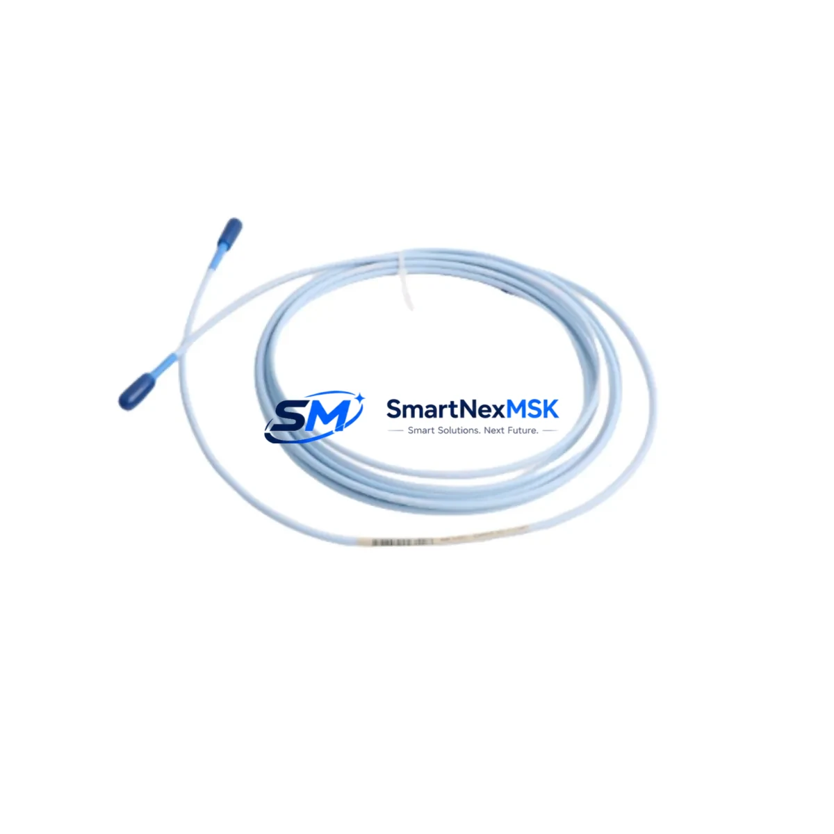
Bently Nevada 330130-040-00-00/CN Spare for 3300 XL Automation: Spare Replacement & Industrial Downtime Risk Control
The Bently Nevada 330130-040-00-00/CN is a 40-foot (approximately 12.2 m) proximity extension cable engineered for use within the 3300 XL Proximity Transducer System — one of the most widely deployed vibration and position monitoring platforms in rotating machinery protection. This cable serves as the critical signal transmission link between the 3300 XL proximitor/driver and the eddy-current probe tip, carrying low-level analog signals that feed directly into the 3500 Series Machinery Protection System or equivalent rack-based monitors. Maintaining a verified spare of this cable in your site inventory is a fundamental requirement for any maintenance program targeting zero unplanned downtime on turbines, compressors, pumps, and gearboxes.
For maintenance engineers managing condition monitoring infrastructure, the 330130-040-00-00/CN is not an isolated component — it is part of a tightly integrated measurement chain. When this cable is replaced during a planned outage or emergency callout, the surrounding system must be inspected and validated in parallel to ensure signal integrity is fully restored before the machine is returned to service.
Spare Maintenance Table
| Parameter | Specification / Detail |
|---|---|
| Part Number | 330130-040-00-00/CN |
| Brand | Bently Nevada |
| Series | 3300 XL Proximity Transducer System |
| Product Type | Proximity Extension Cable |
| Cable Length | 40 ft (approx. 12.2 m) |
| Connector Type | Coaxial, compatible with 3300 XL probe and proximitor |
| Signal Type | Analog eddy-current (low-level, high-impedance) |
| Compatible Systems | Bently Nevada 3300 XL, 3500 Series Machinery Protection System |
| Compatible Probes | 330100, 330101, 330103 series eddy-current probes |
| Compatible Proximitors | 330180, 330185 series proximitor/driver modules |
| Installation Environment | Industrial — turbine halls, compressor stations, pump skids |
| Temperature Range | -40°C to +85°C (cable jacket rated) |
| Origin | USA (OEM) |
| Condition | Original spare, tested before shipment |
| Warranty | 12 months from date of shipment |
| Lead Time | In-stock — ships within 3 business days |
Maintenance Planning for Continuous Operation
When a 330130-040-00-00/CN extension cable is flagged for replacement — whether due to physical damage, connector corrosion, signal drift, or scheduled life-cycle renewal — the maintenance window should be used to inspect and verify the entire proximity measurement loop. Begin with the eddy-current probe tip (typically a 330100 or 330103 series probe): check for tip damage, contamination, and correct gap setting using a calibrated gap tool. The proximitor/driver module (such as the 330180 or 330185) should be tested for output voltage linearity and confirmed to be within the –18 VDC to –24 VDC supply range before reconnecting the new cable.
At the rack level, verify that the 3500/40M or 3500/42M proximitor I/O module is receiving clean power from the 3500/15 Power Supply module. A degraded power supply is a common root cause of intermittent signal faults that are incorrectly attributed to the extension cable. While the cabinet is open, inspect the 3500/20 Rack Interface Module for firmware currency and communication health, particularly if the system feeds a DCS historian or safety instrumented system via Modbus or FOUNDATION Fieldbus.
Terminal blocks and field wiring terminations at the junction box should be torqued to specification and inspected for oxidation — especially in humid or offshore environments. If the plant uses signal isolators between the proximitor output and the DCS analog input card, verify that the isolator (such as a DIN-rail mounted 4–20 mA loop isolator) is within calibration. Shielding continuity along the full cable run — from probe tip through extension cable to proximitor — must be confirmed to prevent ground loops that corrupt vibration readings.
For sites running legacy 3300 Series monitors alongside newer 3500 racks, the 330130-040-00-00/CN is compatible with both platforms, making it a versatile stocking item. Procurement engineers should consider holding at least two units per critical machine train, particularly for high-speed turbines or compressors where a proximity system fault triggers an automatic trip. Pairing this cable spare with a stocked 330180 proximitor and a 330100 probe tip creates a complete field-replaceable measurement chain that can restore monitoring capability within a single shift.
Site Replacement Workflow
Step 1 — Isolation and Permit: Obtain a work permit and isolate the measurement channel at the 3500 rack. Place the affected channel in bypass mode to prevent a spurious trip during cable replacement. Document the pre-replacement gap voltage and vibration baseline from the operator HMI or System 1 condition monitoring software.
Step 2 — Cable Removal: Disconnect the existing 330130-040-00-00/CN at both the probe junction and the proximitor input. Inspect connectors for corrosion, bent pins, or damaged ferrules. If the old cable shows jacket cracking or connector wear, photograph and tag for failure analysis.
Step 3 — New Cable Installation: Route the replacement 330130-040-00-00/CN along the existing cable tray, maintaining separation from high-voltage power cables. Torque connectors to the manufacturer’s specified value. Verify shield continuity with a multimeter before energizing.
Step 4 — Gap and Signal Verification: With the proximitor powered, measure the output DC voltage at the proximitor output terminal. Adjust probe gap if necessary to achieve the target voltage (typically –10 VDC ±0.5 VDC at nominal gap). Confirm the reading matches the pre-replacement baseline within acceptable tolerance.
Step 5 — Channel Reinstatement: Remove the bypass, confirm the 3500 rack is displaying healthy channel status, and verify that the DCS or historian is receiving the correct vibration and position values. Update the maintenance record with the new cable serial number, installation date, and post-replacement gap voltage.
This workflow applies equally when upgrading from an older 330130 series cable to the current 330130-040-00-00/CN revision, ensuring backward compatibility is maintained without requiring recalibration of the full measurement chain.
Spare Parts Support FAQ
Q1: Is the 330130-040-00-00/CN a direct replacement for earlier 330130 series extension cables?
Yes. The 330130-040-00-00/CN is the current OEM revision and is backward-compatible with all 3300 XL and legacy 3300 Series proximity systems. No modification to the proximitor or probe is required when substituting an earlier revision with this part number.
Q2: How is each unit tested before shipment?
Every 330130-040-00-00/CN unit undergoes continuity testing, connector integrity verification, and shield resistance measurement prior to packaging. Units are shipped with a test record and are covered by a 12-month warranty from the date of shipment against manufacturing defects.
Q3: What is the recommended stocking strategy for this cable?
For critical rotating machinery (turbines, centrifugal compressors, boiler feed pumps), we recommend a minimum of two units per machine train in on-site inventory. For plants with five or more monitored machines, a centralized spare pool of four to six units reduces per-machine holding cost while maintaining rapid response capability for emergency replacements.
Q4: Can this cable be used with non-Bently Nevada eddy-current systems?
The 330130-040-00-00/CN is designed and calibrated for the Bently Nevada 3300 XL measurement chain. While the coaxial connector format may be physically compatible with some third-party proximitor systems, signal accuracy and system certification cannot be guaranteed outside the Bently Nevada ecosystem. For cross-brand compatibility, consult your instrumentation engineer before installation.
© 2026 SMARTNEXMSK. All rights reserved.
Original Source: https://smartnexmsk.com
Contact: [email protected] | +86 18259474341



