
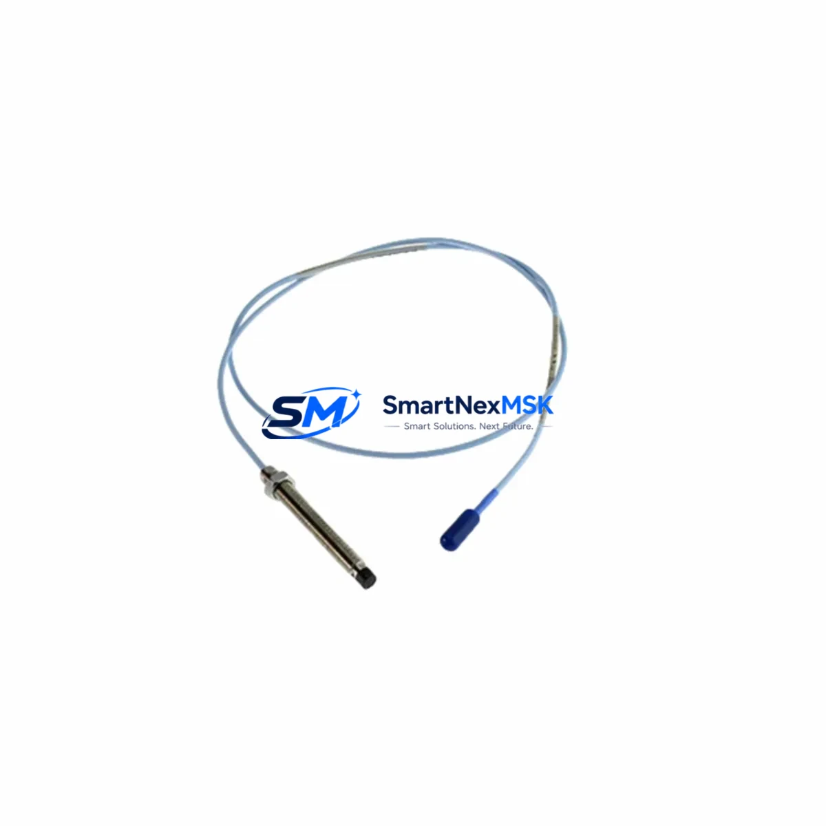
Bently Nevada 330130-045-12-00 Retrofit-Ready Extension Cable for 3300 XL Control Systems
The Bently Nevada 330130-045-12-00 is a 45-foot (approximately 13.7 m) coaxial extension cable engineered for use within the 3300 XL proximity transducer system — one of the most widely deployed vibration monitoring platforms in rotating machinery protection. As legacy installations age and OEM support windows close, this cable remains a critical link between the proximity probe and the Bently Nevada 3300 XL proximitor/driver, making it an essential component in both planned system upgrades and emergency spare-part replacements.
Whether you are modernizing a turbine protection panel, retrofitting a compressor train monitoring rack, or restoring a dormant machine protection system, the 330130-045-12-00 provides a verified drop-in replacement path that preserves signal integrity without requiring re-engineering of the transducer chain. Its impedance-matched construction ensures compatibility with the full 3300 XL probe-and-driver assembly, including the 330101 series proximity probes and the 330180 proximitor drivers commonly installed in gas turbine, steam turbine, and centrifugal compressor applications.
Upgrade Compatibility Table
| Parameter | 330130-045-12-00 Specification | Retrofit Notes |
|---|---|---|
| Cable Length | 45 ft (13.7 m) | Verify total probe-to-driver distance; standard 3300 XL chain = 5 m probe + 5 m extension + driver |
| Connector Type | BNC coaxial, both ends | Confirm mating connector condition on proximitor driver housing before installation |
| System Compatibility | Bently Nevada 3300 XL Series | Not interchangeable with 7200 Series or 3500 Series without signal chain recalibration |
| Replacement Models | Supersedes 330130-045-00-00 (non-armored) | Armored jacket version preferred for high-vibration or high-temperature environments |
| Communication Protocol | Analog (eddy-current signal, –18 VDC bias) | Confirm proximitor output range matches 3500/22M or 3500/40M monitor card input spec |
| Installation Requirement | Conduit or cable tray routing | Maintain minimum bend radius; avoid routing near high-voltage power cables |
| Commissioning Check | Gap voltage verification at proximitor output | Target –10.0 VDC ±0.5 V at nominal air gap; document baseline before system handover |
| Warranty | 12 Months | Covers manufacturing defects; includes pre-shipment continuity and impedance test report |
Retrofit Planning for Existing Automation Systems
Successful integration of the 330130-045-12-00 into an existing machine protection architecture requires a structured pre-installation review. Begin by auditing the full transducer chain: the 330101-00-08-10-02-00 proximity probe, the existing extension cable routing path, and the 330180-X1-05 proximitor driver mounted in the field junction box or control cabinet. If the proximitor driver is also end-of-life, consider replacing it simultaneously with a current-production 330180 unit to avoid a second outage window.
Inside the control cabinet, the 3500/22M transient data interface or the 3500/40M proximitor I/O module receives the conditioned signal from the proximitor. Verify that the monitor card’s channel configuration — gap range, scale factor, and OK relay setpoints — matches the new cable’s electrical characteristics. If the plant is migrating from an older 3300 rack to a 3500 Series rack, the 3500/01 rack power supply and 3500/05 system rack must be confirmed as correctly sized for the expanded I/O count before the extension cable is terminated.
For plants running a DCS integration layer — such as an Emerson Ovation controller or a Honeywell Experion PKS node — confirm that the 4–20 mA or Modbus RTU output from the 3500 monitor card is correctly mapped to the DCS historian tag before the machine is returned to service. HMI screens displaying vibration trend data should be validated against the new baseline gap voltage to prevent nuisance alarms during the first run-up cycle.
Where the control cabinet includes a Bently Nevada 3500/92 communication gateway or a TDI Modbus interface, verify that the rack address and channel assignments are unchanged after the cable swap. Any change in proximitor sensitivity (mV/mil) caused by substituting a different cable length must be reflected in the monitor card’s scale factor configuration and in the DCS engineering unit conversion block.
Technicians should also inspect the 3500/15 power supply module output voltage under load before energizing the new transducer chain. A degraded power supply can produce intermittent OK relay dropouts that are difficult to distinguish from a faulty extension cable, wasting diagnostic time during a planned outage.
Downtime Control During System Migration
Minimizing unplanned downtime during a proximity transducer cable replacement requires pre-staging all components — including the 330130-045-12-00 extension cable, spare BNC termination tools, and a calibrated gap-setting fixture — before the machine is taken offline. A pre-written loop check procedure, referencing the original installation drawing and the 3500 rack configuration file, allows the commissioning team to work through gap voltage verification, OK relay confirmation, and DCS tag validation in a single shift.
Where the plant operates a redundant monitoring channel (common in API 670-compliant installations), the replacement can be performed on the standby channel while the primary channel remains in service, eliminating the need for a full machine shutdown. After the new cable is terminated and the gap voltage is confirmed, the channels can be switched over with no interruption to the protection logic.
Original PLC or DCS program logic does not require modification for a like-for-like cable replacement, provided the proximitor sensitivity and monitor card scale factor remain unchanged. Retain a copy of the 3500 rack configuration file (exported via System 1 software or the 3500 Rack Configuration Utility) before and after the work to support post-maintenance audit requirements.
Retrofit Support FAQ
Q: Is the 330130-045-12-00 a direct replacement for the 330130-045-00-00?
A: Yes. The -12-00 suffix denotes the armored cable jacket variant, which provides additional mechanical protection in high-vibration environments. The electrical characteristics — impedance, sensitivity, and connector type — are identical, making it a drop-in replacement without recalibration.
Q: What gap voltage should I expect after installation?
A: With a standard 330101 series probe at nominal air gap (typically 1.0 mm / 40 mil), the proximitor output should read approximately –10.0 VDC ±0.5 V. Deviations outside this range indicate a gap adjustment is required or that the proximitor driver needs replacement.
Q: Can this cable be used with a 3500 Series monitor rack instead of a 3300 XL rack?
A: The 330130-045-12-00 is compatible with any Bently Nevada system that accepts a standard 3300 XL transducer chain output. When integrating with a 3500/22M or 3500/40M monitor card, confirm the channel’s configured sensitivity matches the proximitor driver’s output specification.
Q: What does the 12-month warranty cover?
A: The warranty covers manufacturing defects in materials and workmanship. Each unit undergoes pre-shipment continuity and impedance testing. A test report is available upon request. Warranty claims are processed within 5 business days of receipt of the returned unit.
© 2026 SMARTNEXMSK. All rights reserved.
Original Source: https://smartnexmsk.com
Contact: [email protected] | +86 18259474341



