
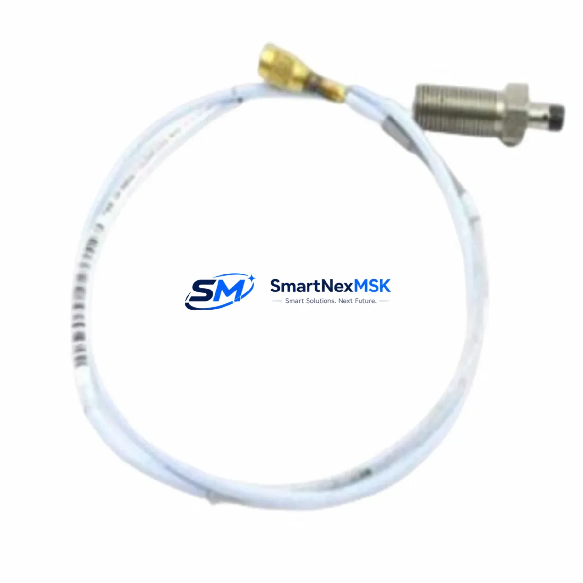
Bently Nevada 330130-080-00-CN Maintenance-Ready Spare 3300 XL Automation
The Bently Nevada 330130-080-00-CN is an 8-metre proximity transducer extension cable engineered for the 3300 XL continuous vibration monitoring system. As a direct OEM-equivalent spare, it bridges the gap between the proximitor/driver and the eddy-current probe in rotating-machinery protection loops — turbines, compressors, pumps, and gearboxes operating under API 670 requirements. When a cable fault triggers a high-vibration trip or a false Danger alarm, every minute of unplanned downtime translates into measurable production loss. Stocking a verified 330130-080-00-CN spare eliminates that risk and restores normal monitoring within a single shift.
Maintenance engineers working on Bently Nevada 3300 XL or 3500 Series racks recognise that the extension cable is the most mechanically stressed element in the proximity measurement chain. Repeated thermal cycling, cable tray abrasion, connector corrosion, and vibration fatigue degrade the coaxial impedance and introduce measurement offset errors that are difficult to distinguish from genuine shaft movement. Replacing the cable on a planned basis — rather than waiting for a confirmed fault — is the lowest-cost intervention in the predictive-maintenance toolkit.
Spare Maintenance Table
| Parameter | Specification |
|---|---|
| Part Number | 330130-080-00-CN |
| Brand | Bently Nevada |
| Series | 3300 XL Proximity System |
| Cable Length | 8 metres (26.2 ft) |
| Cable Type | Coaxial, armoured extension |
| Connector Style | MIL-spec threaded, gold-plated |
| Characteristic Impedance | 95 Ω nominal |
| System Compatibility | Bently Nevada 3300 XL, 3500 Series, 7200 Series proximitors |
| Probe Compatibility | 3300 XL 8mm, 11mm, 14mm eddy-current probes |
| Operating Temperature | −40 °C to +121 °C |
| Installation Environment | Turbine bearing pedestals, compressor skids, pump bearing housings |
| Maintenance Interval | Inspect every 12 months; replace on impedance drift or connector damage |
| Warranty | 12 Months — tested before shipment |
| Origin | United States |
| Condition | Original spare, new or surplus-tested |
Maintenance Planning for Continuous Operation
A structured spare-parts strategy for a Bently Nevada 3300 XL or 3500 rack goes well beyond the extension cable itself. During a planned outage or a corrective-maintenance window, experienced maintenance engineers treat the 330130-080-00-CN replacement as the trigger for a broader inspection of the entire proximity measurement loop and the associated monitoring rack.
Start at the probe end: the Bently Nevada 330130-040-00-CN (4 m extension) or the matching 3300 XL 8 mm eddy-current probe (e.g. 330101-00-06-10-02-00) should be gap-checked and impedance-verified before the new cable is terminated. A worn probe tip or a cracked probe body will produce the same erratic gap voltage as a faulty cable, so confirming probe integrity first avoids a repeat callout.
At the rack end, inspect the 3300 XL proximitor/driver module (typically a 330180-X1-05 or equivalent) for bias voltage stability. A proximitor that is drifting outside its −18 VDC nominal output will corrupt the gap measurement regardless of cable condition. If the rack houses a Bently Nevada 3500/42M or 3500/44M vibration monitor card, verify that the OK relay output and the buffered output BNC connectors are clean and making solid contact — these are common failure points in high-vibration environments.
Power integrity is equally critical. The 3500/15 Power Supply module and its redundant companion should be load-tested; a sagging DC rail causes false OK dropouts that mimic cable faults. Check the 3500/20 Rack Interface Module (RIM) for firmware currency and communication health — a RIM that is dropping Modbus or RS-232 frames will generate nuisance alarms that mask genuine mechanical faults.
For facilities running older Bently Nevada 7200 Series proximitors alongside newer 3300 XL hardware, confirm that the extension cable impedance matches the proximitor’s tuned system — mixing 3300 XL cables with 7200 Series proximitors without recalibration introduces a systematic gap error. In these legacy-extension scenarios, a 3300 XL System Calibrator (190501-01) is an essential bench tool for verifying the complete probe-cable-proximitor chain before returning the machine to service.
Finally, review the terminal block wiring inside the junction box. Corroded Phoenix Contact or Weidmüller terminal strips, loose ferrules, and degraded cable glands are responsible for a disproportionate share of intermittent proximity faults. Replacing the extension cable while leaving corroded terminations in place simply relocates the failure point. A complete loop verification — probe → extension cable → junction box → proximitor → monitor card — is the only way to certify that the measurement chain is fit for continued service.
Site Replacement Workflow
Step 1 — Isolate and document. Before disconnecting the existing 330130-080-00-CN, record the as-found gap voltage (typically −10 VDC ±0.5 V for an 8 mm probe at 1.0 mm gap) using a calibrated digital voltmeter at the proximitor output. This baseline confirms whether the cable — rather than the probe or proximitor — is the root cause of the fault.
Step 2 — Verify replacement part. Confirm that the replacement cable carries the correct part number suffix (-CN denotes the Chinese-market coaxial specification). Check connector thread condition and coaxial continuity with an LCR meter or cable tester before routing the cable through the conduit or cable tray.
Step 3 — Install and terminate. Route the new cable following the original path to avoid introducing additional bend radius stress. Torque MIL-spec connectors to the manufacturer’s specification (typically 0.9–1.1 N·m). Avoid parallel routing with high-voltage power cables for more than 300 mm to prevent capacitive coupling noise on the coaxial shield.
Step 4 — Commission and verify. With the machine at rest, confirm gap voltage is within the system’s calibrated range. Enable the monitor channel and verify that the OK relay energises and that vibration and position readings are within expected idle values. Log the as-left gap voltage in the maintenance management system (CMMS) for future trend comparison.
Step 5 — Return to service. Clear any latched alarms at the 3500/20 RIM or DCS interface, confirm that the historian is logging the channel, and update the spare-parts inventory to trigger a replenishment order for the next 330130-080-00-CN unit. Total elapsed time for a prepared maintenance team: 2–4 hours including documentation.
Spare Parts Support FAQ
Q1: Is the 330130-080-00-CN compatible with both 3300 XL and 3500 Series monitoring systems?
Yes. The 330130-080-00-CN extension cable is designed for the Bently Nevada 3300 XL proximity system and is electrically compatible with 3500 Series proximitor/driver modules that share the same 95 Ω coaxial specification. Always verify the proximitor model number and system calibration before installation to confirm the complete probe-cable-proximitor chain is matched.
Q2: How should I manage inventory levels for this cable in a multi-machine facility?
Industry best practice for rotating-machinery protection spares is to hold a minimum of one cable per monitored shaft, with an additional buffer of 20–25% for emergency callouts. For facilities with 10 or more monitored machines, a standing replenishment order triggered at two units on hand is recommended. The 12-month warranty on each unit supports a rolling stock rotation strategy without risk of holding expired inventory.
Q3: What pre-shipment testing is performed on each 330130-080-00-CN unit?
Each cable undergoes coaxial continuity verification, characteristic impedance measurement, and connector integrity inspection before dispatch. Units that fail any parameter are quarantined and not shipped. A test record is available on request. This process ensures that the replacement cable performs to OEM specification from the moment it arrives on site.
Q4: Can this cable replace older Bently Nevada 330130 series cables with different length suffixes?
The -080 suffix designates an 8-metre cable. It cannot be substituted for shorter lengths (e.g. -040 for 4 m or -020 for 2 m) without recalibrating the proximity system, because total system length — probe plus extension — determines the proximitor’s tuned gap range. If your existing installation uses a different length, contact us with your proximitor model and probe part number to confirm the correct replacement cable length before ordering.
© 2026 SMARTNEXMSK. All rights reserved.
Original Source: https://smartnexmsk.com
Contact: [email protected] | +86 18259474341



