
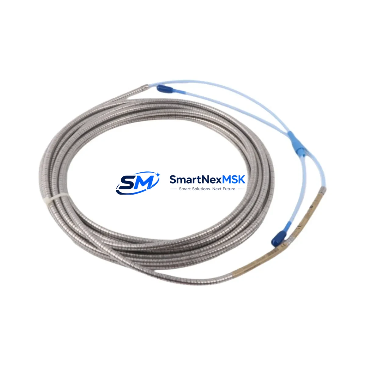
Bently Nevada 330130-085-12-00 Retrofit-Ready Extension Cable for 3300 XL Control Systems
The Bently Nevada 330130-085-12-00 is a precision-engineered proximity transducer extension cable designed for seamless integration into the 3300 XL Proximity Transducer System. As legacy vibration monitoring infrastructure ages across rotating machinery applications — including turbines, compressors, pumps, and gearboxes — the demand for verified drop-in replacements has grown significantly. This cable serves as a direct retrofit solution for facilities managing end-of-life components, discontinued spare parts, or control cabinet upgrades without full system replacement.
Whether you are restoring a degraded signal chain, replacing a mechanically damaged cable run, or modernizing a monitoring rack, the 330130-085-12-00 delivers the electrical and mechanical compatibility required to maintain continuous vibration data integrity. The cable is manufactured to match the original Bently Nevada specification, ensuring correct impedance, shielding, and connector interface for use with the 3300 XL proximitor/driver and associated field-mounted transducers.
Upgrade Compatibility Table
| Parameter | Detail |
|---|---|
| SKU / Part Number | 330130-085-12-00 |
| Brand | Bently Nevada |
| Compatible System | 3300 XL Proximity Transducer System |
| Cable Length | 8.5 m (28 ft) — suffix -085 denotes 8.5 m |
| Connector Interface | Standard Bently Nevada coaxial connector, compatible with 3300 XL proximitor inputs |
| Replaces / Supersedes | 330130-085-12-00 (original), compatible with legacy 3300 series extension cable positions |
| Installation Requirement | No hardware modification required; direct plug-in replacement |
| Communication Compatibility | Passive cable — compatible with all 3300 XL signal conditioning configurations |
| Retrofit Recommendation | Verify total cable system length (transducer + extension) does not exceed proximitor specification |
| Commissioning Note | Confirm gap voltage and static voltage readings post-installation using Bently Nevada calibration procedure |
| Warranty | 12 Months from date of shipment |
Retrofit Planning for Existing Automation Systems
Integrating the 330130-085-12-00 into an existing monitoring architecture requires a structured approach to avoid signal errors and unplanned downtime. In a typical 3300 XL installation, the extension cable bridges the gap between the field-mounted 3300 XL 8 mm or 11 mm proximity transducer and the 3300 XL proximitor/driver module housed in the monitoring rack. Before replacement, engineers should verify the total cable system length — the sum of the transducer armored cable and the extension cable — remains within the proximitor’s specified range, typically 5 m or 9 m system configurations.
In control cabinet upgrade scenarios, the 330130-085-12-00 is commonly installed alongside the 3300 XL 16-Channel Relay Module and the 3500/22M Transient Data Interface, where vibration signal continuity is critical for machinery protection logic. When migrating from older 3300 series racks to the 3500 series platform, the extension cable routing and connector labeling should be documented before disconnection to preserve channel-to-bearing mapping in the System 1 condition monitoring software.
For facilities running Bently Nevada 3500/42M Proximitor I/O Modules or 3500/40M Proximitor I/O Modules, the 330130-085-12-00 extension cable remains compatible provided the proximitor input impedance and bias voltage specifications are matched. Technicians should also inspect the junction box or field terminal block for corrosion or connector wear before installing the replacement cable, as degraded terminations can introduce noise into the vibration signal chain even with a new cable in place.
In multi-channel rack configurations using the 3500/15 Power Supply Module, confirm that the rack power budget accommodates all active proximitor channels during the retrofit window. Where the existing installation includes a 3300 XL Dual Voting Trip Module, verify that the relay logic and setpoint configuration are preserved in the System 1 database before any cable swap to prevent spurious trips during commissioning.
For sites using Modbus or FOUNDATION Fieldbus communication links between the 3500 rack and the DCS or SCADA layer, the cable replacement itself does not affect the communication protocol. However, if the retrofit is part of a broader migration from the 3300 platform to the 3500 platform, the I/O mapping in the DCS — including the Emerson DeltaV or Honeywell Experion historian tags — must be updated to reflect any channel renumbering introduced by the new rack layout. Programming cables such as the Bently Nevada 3500 Configuration Cable should be on hand during commissioning to allow real-time parameter verification.
Downtime Control During System Migration
Minimizing production interruption during a proximity transducer cable replacement requires pre-staging all materials and completing as much preparation as possible during scheduled maintenance windows. Before the planned outage, technicians should photograph the existing cable routing, label both ends of the 330130-085-12-00 with the corresponding channel and bearing designation, and export the current System 1 configuration as a backup file. This preserves the original alarm setpoints, gap voltage targets, and dynamic data acquisition parameters.
During the replacement, the 3300 XL proximitor channel should be placed in bypass mode — if supported by the rack configuration — to prevent a false trip signal from propagating to the machinery protection relay output while the cable is disconnected. After the new 330130-085-12-00 is installed and terminated, the gap voltage should be measured at the proximitor front panel or via the System 1 interface to confirm the probe is correctly positioned within the linear range, typically between -10 VDC and -18 VDC for standard 3300 XL configurations.
Once gap voltage is confirmed, the channel bypass should be removed and the dynamic vibration reading verified against baseline values recorded prior to the outage. If the overall vibration level or 1X amplitude deviates significantly from the pre-outage baseline, the cable terminations, connector seating, and total cable system length should be re-inspected before returning the machine to service. All commissioning steps should be documented in the site maintenance management system to support future audits and warranty claims.
Retrofit Support FAQ
Q: Is the 330130-085-12-00 a direct drop-in replacement for the original Bently Nevada part?
A: Yes. This cable is manufactured to match the original Bently Nevada 330130-085-12-00 specification, including connector type, cable length (8.5 m), shielding, and impedance characteristics. No wiring modification or adapter is required for installation in a standard 3300 XL system.
Q: Can this extension cable be used with the Bently Nevada 3500 series platform?
A: The 330130-085-12-00 is specified for the 3300 XL Proximity Transducer System. Compatibility with 3500 series proximitor modules depends on the specific I/O module and cable system length configuration. We recommend verifying the proximitor input specification before installation in a 3500 series rack.
Q: What pre-shipment testing is performed on this cable?
A: Each unit undergoes continuity testing, shield integrity verification, and connector interface inspection prior to shipment. A test report is available upon request. All units are covered by a 12-month warranty from the date of shipment.
Q: What information should I provide when ordering to confirm compatibility?
A: Please provide the proximitor model number (e.g., 3300 XL 8 mm Proximitor), the existing cable system length, and the machine type. This allows our technical team to confirm that the 330130-085-12-00 is the correct extension cable for your application before shipment.
© 2026 SMARTNEXMSK. All rights reserved.
Original Source: https://smartnexmsk.com
Contact: [email protected] | +86 18259474341



