
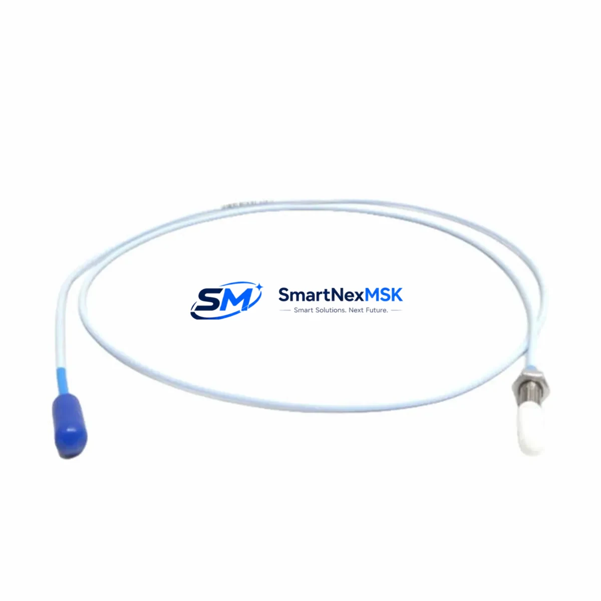
Bently Nevada 330171-00-08-10-02-00 Spare 3300 XL Automation: Precision Spare Parts Replacement for Vibration Monitoring Continuity
The Bently Nevada 330171-00-08-10-02-00 is an 8mm proximity probe engineered for the 3300 XL Proximity Transducer System — one of the most widely deployed continuous vibration monitoring platforms in rotating machinery applications across power generation, oil & gas, petrochemical, and heavy industrial sectors. When this probe fails or degrades, the entire vibration channel goes dark, leaving critical rotating assets — turbines, compressors, pumps, and gearboxes — unmonitored and exposed to catastrophic failure risk.
Sourced as an original Bently Nevada spare, the 330171-00-08-10-02-00 is built to the same dimensional, electrical, and sensitivity specifications as the factory-installed unit. It integrates directly with the 3300 XL extension cable and 3300 XL proximitor/driver without recalibration, making it the preferred choice for maintenance engineers who need a verified drop-in replacement with zero commissioning delay. Every unit is tested prior to dispatch and ships with a 12-month warranty covering manufacturing defects and performance conformance.
For maintenance planners and procurement engineers managing aging 3300 XL installations, holding at least one 330171-00-08-10-02-00 in the on-site spare parts cabinet is a standard risk mitigation practice. Probe degradation is often gradual — gap voltage drift, sensitivity loss, or intermittent signal dropout — and is frequently misdiagnosed as a proximitor fault or cable issue before the probe itself is identified as the root cause. Having a verified spare on hand eliminates the diagnostic ambiguity and compresses the mean time to repair (MTTR) from days to hours.
Spare Maintenance Table
| Parameter | Specification |
|---|---|
| Part Number / SKU | 330171-00-08-10-02-00 |
| Brand | Bently Nevada |
| Series | 3300 XL Proximity Transducer System |
| Probe Type | Eddy-Current Proximity Probe, 8mm |
| Probe Tip Diameter | 8 mm |
| Cable Length | 1.0 m (integral cable; extension cable ordered separately) |
| Armor / Jacket | Stainless steel armored, PTFE-jacketed cable |
| Sensitivity | 7.87 V/mm (200 mV/mil) nominal |
| Linear Range | 0.25 – 2.54 mm (10 – 100 mil) |
| Supply Voltage | –24 VDC (via proximitor/driver) |
| Operating Temperature | –35°C to +177°C (probe body) |
| Target Material Compatibility | Steel, stainless steel, iron alloys (standard calibration) |
| Connector | 3-pin MIL-C-5015 style (mates with 3300 XL extension cable) |
| Mounting Thread | M10 × 1.0 (standard) |
| Installation Environment | Bearing housings, seal areas, thrust collars; IP67 rated |
| Compatible Proximitor | 3300 XL 8mm Proximitor (e.g., 330180-X1-CN) |
| Compatible Extension Cable | 330130-080-XX-CN (8mm, various lengths) |
| Maintenance Recommendation | Replace at first sign of gap voltage drift >±0.5 V from baseline; inspect connector and armor annually |
| Warranty | 12 Months — covers manufacturing defects and performance conformance |
| Origin | USA (Bently Nevada / Baker Hughes) |
| Condition | Original New Spare |
Maintenance Planning for Continuous Operation
A proximity probe replacement is rarely an isolated event. When a 330171-00-08-10-02-00 is pulled from service, a disciplined maintenance engineer uses the opportunity to inspect the entire vibration channel and adjacent control cabinet components before the machine is returned to operation.
Begin with the 3300 XL extension cable (330130-080-XX-CN) — the most common source of signal degradation after the probe itself. Inspect the armor jacket for kinking, abrasion, or heat damage near the bearing housing exit. Check both connectors for corrosion or pin damage. A probe replacement paired with a worn extension cable will reproduce the original fault within weeks.
Next, verify the 3300 XL 8mm Proximitor/Driver (330180-X1-CN). Measure the output voltage at the nominal gap distance and confirm it falls within the ±0.5 V tolerance of the calibration curve. A proximitor that has drifted outside specification will produce incorrect vibration readings even with a new probe installed. If the proximitor is original to the installation and has not been replaced in over five years, treat it as a concurrent spare candidate.
Inspect the 3300 XL I/O module and its terminal block connections in the machinery protection rack. Loose or oxidized terminals on the –24 VDC supply line and signal return are a frequent source of intermittent channel faults that are misattributed to the probe. Torque all terminals to specification and apply contact enhancer where appropriate.
For installations using a 3500 Series Machinery Protection System rack alongside legacy 3300 XL channels, verify that the 3500/42M Proximitor I/O Module is correctly configured for 8mm probe sensitivity. A mismatch between the I/O module configuration and the installed probe type will produce scaled vibration errors that are difficult to detect without a calibration check.
Review the power supply module feeding the 3300 XL rack — typically a –24 VDC regulated supply. Measure output voltage under load and confirm ripple is within specification. A sagging or noisy supply will introduce baseline noise into all vibration channels simultaneously, which can mask real machinery faults.
Where the vibration signal feeds into a DCS or safety system via a 4–20 mA signal conditioner or signal isolator, verify the isolator output range and zero/span calibration. Signal isolators age and drift; a channel that reads correctly at the proximitor output may be presenting a scaled error at the DCS input. This is particularly relevant in older installations where the isolator has not been included in the calibration schedule.
Finally, check any relay output modules or trip amplifiers associated with the vibration channel. Confirm that alert and danger setpoints are correctly programmed and that the relay contacts are clean and functional. A probe replacement that restores the vibration signal to a healthy level should be followed by a functional test of the trip relay to confirm the protection chain is intact end-to-end.
For sites running Bently Nevada System 1 software for online machinery diagnostics, update the channel configuration after probe replacement to reset the baseline gap voltage and confirm the new probe’s sensitivity coefficient is correctly entered. Failure to update the software configuration is a common post-maintenance oversight that results in incorrect vibration amplitude readings in the trending database.
Site Replacement Workflow
Step 1 — Pre-replacement verification. Before removing the installed probe, record the current gap voltage at the proximitor output (typically –10 to –18 VDC for a healthy 8mm probe at nominal gap). This baseline confirms whether the fault is in the probe, the extension cable, or the proximitor, and provides a reference for post-installation verification of the new unit.
Step 2 — Isolation and lockout. Follow site LOTO procedures. De-energize the –24 VDC supply to the affected channel at the rack. Do not de-energize the entire rack if other channels must remain in service — the 3300 XL system supports individual channel isolation.
Step 3 — Probe removal. Unthread the probe from the bearing housing using the correct spanner. Note the installed gap (number of turns from flush) for reference. Inspect the probe tip for impact damage, contamination, or corrosion. Inspect the housing threads for damage.
Step 4 — New probe installation. Thread the 330171-00-08-10-02-00 into the housing and set the gap to the value specified on the machine data sheet (typically 1.0–1.5 mm for most rotating machinery applications). Lock the probe in position with the locknut. Connect the extension cable and verify the connector is fully seated and locked.
Step 5 — Post-installation verification. Re-energize the channel and measure the gap voltage at the proximitor output. Confirm the reading is within ±0.5 V of the expected value for the set gap distance. Verify the vibration reading in the monitoring system is stable and consistent with the machine’s known baseline. Confirm alert and danger setpoints are active.
Step 6 — Documentation. Record the replacement in the maintenance management system (CMMS) with the new probe serial number, installation date, gap setting, and post-installation gap voltage. Update the spare parts inventory to trigger reorder of a replacement spare, maintaining the minimum stock level.
This workflow applies equally to planned maintenance replacements and emergency unplanned outages. The 330171-00-08-10-02-00 is a direct replacement for earlier 330171 series probes with the same 8mm tip diameter and 3300 XL system compatibility, eliminating the need for recalibration or system reconfiguration when substituting for an older installed unit.
Spare Parts Support FAQ
Q1: Is the 330171-00-08-10-02-00 a direct replacement for other 330171 series variants?
Yes. The 330171-00-08-10-02-00 is part of the Bently Nevada 330171 8mm probe family and is dimensionally and electrically compatible with other 330171 variants sharing the same tip diameter, connector type, and 3300 XL system designation. Always verify the cable length suffix and armor specification against your machine data sheet before installation. If your installed probe has a different cable length, the extension cable (330130 series) compensates for the difference without affecting system calibration.
Q2: What is the recommended spare parts inventory strategy for 3300 XL proximity probes?
For critical rotating machinery (turbines, compressors, large pumps), the industry standard is a minimum of one probe per monitored channel held on-site, with an additional buffer of 10–20% of total installed probes held in the central warehouse. For facilities with 20 or more 3300 XL channels, a standing purchase order or blanket agreement with a verified supplier ensures replenishment lead times do not exceed 72 hours. The 330171-00-08-10-02-00 should be stored in its original packaging in a temperature-controlled environment away from strong magnetic fields.
Q3: How is each unit tested before shipment?
Every 330171-00-08-10-02-00 unit supplied by SMARTNEXMSK undergoes pre-shipment functional verification including gap voltage output measurement at a calibrated test gap, sensitivity confirmation against the 7.87 V/mm nominal specification, connector integrity check, and cable continuity and insulation resistance test. Units that do not meet specification are quarantined and not dispatched. A test report is available upon request for quality-critical applications.
Q4: What does the 12-month warranty cover, and what is the claims process?
The 12-month warranty covers manufacturing defects, out-of-specification sensitivity, connector failure, and cable jacket integrity under normal installation and operating conditions. It does not cover damage resulting from incorrect installation, mechanical impact, chemical exposure beyond the probe’s rated environment, or operation outside the specified supply voltage range. To initiate a warranty claim, contact [email protected] with the order number, unit serial number, fault description, and installation date. Replacement units are dispatched within 5 business days of claim verification.
© 2026 SMARTNEXMSK. All rights reserved.
Original Source: https://smartnexmsk.com
Contact: [email protected] | +86 18259474341



