
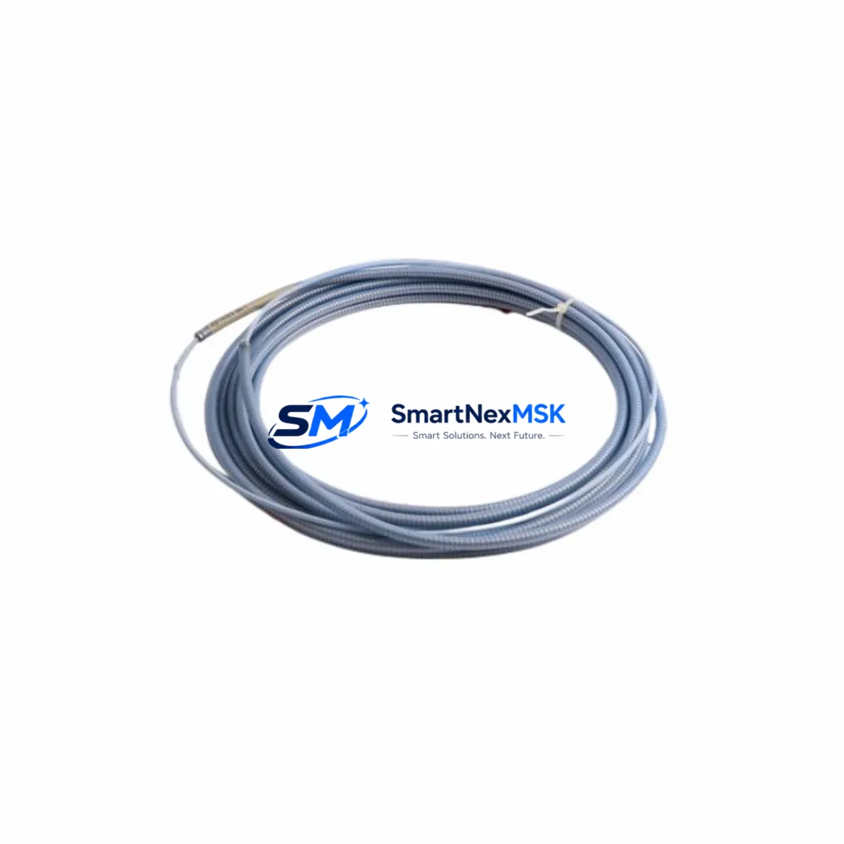
Bently Nevada 330196-05-30-10-CN Retrofit-Ready Proximity Sensor for 3300 XL Control Systems
The Bently Nevada 330196-05-30-10-CN is an eddy-current proximity sensor engineered for the 3300 XL Series continuous machinery monitoring platform. As legacy installations age and original spare parts become increasingly difficult to source, this retrofit-ready replacement provides a verified drop-in solution for facilities managing turbines, compressors, pumps, and rotating machinery where vibration and position monitoring are mission-critical. Whether you are executing a planned control system upgrade or responding to an unplanned failure, the 330196-05-30-10-CN delivers the dimensional accuracy, signal output, and cable termination compatibility required to restore monitoring continuity with minimal downtime.
This sensor operates within the standard Bently Nevada eddy-current measurement chain. It is designed to pair directly with the 3300 XL 8mm Extension Cable and the 3300 XL Proximitor® Signal Conditioner, maintaining the 200 mV/mil output sensitivity that the 3300 XL monitoring system expects. Facilities that have standardized on the 3500 Series Machinery Protection System or are migrating from older 7200 Series installations will find this sensor compatible with the signal conditioning infrastructure already in place, provided the Proximitor module and cable assembly are matched to the correct gap range and driver specifications.
Upgrade Compatibility Table
| Parameter | Specification / Compatibility Note |
|---|---|
| SKU / Part Number | 330196-05-30-10-CN |
| Series Compatibility | Bently Nevada 3300 XL Machinery Monitoring System |
| Sensor Type | Eddy-Current Proximity Sensor (8 mm tip diameter) |
| Cable Length | 5 m (integral cable); extension cable required for full loop |
| Driver / Proximitor | Compatible with 3300 XL Proximitor® Signal Conditioner |
| Output Sensitivity | 200 mV/mil (standard Bently Nevada scale factor) |
| Installation Interface | M10 × 1 threaded body; drop-in for existing sensor brackets |
| Signal Compatibility | Direct replacement — no recalibration of monitor cards required |
| Communication / Protocol | Analog 4–20 mA / voltage output; compatible with 3500 rack I/O modules |
| Replacement Recommendation | Replaces discontinued 330196-05-30-10-CN; verify gap setting post-installation |
| Commissioning Note | Re-establish gap voltage (–10 VDC nominal) after installation; confirm with 3300 XL monitor display |
| Warranty | 12-Month Warranty — covers manufacturing defects and signal output conformance |
Retrofit Planning for Existing Automation Systems
Successful integration of the 330196-05-30-10-CN into an aging control architecture requires a structured pre-installation review. Begin by auditing the existing 3300 XL Extension Cable — typically a 3300 XL 5m or 9m armored cable — for insulation integrity and connector condition. A degraded cable assembly will introduce noise into the measurement loop even with a new sensor installed, so cable replacement should be evaluated in parallel with sensor procurement.
Next, confirm the condition of the 3300 XL Proximitor® Signal Conditioner mounted in the field junction box or control cabinet. If the Proximitor shows drift or erratic gap voltage readings, replacing it alongside the sensor eliminates a common source of post-retrofit diagnostic confusion. For facilities running a 3500/40M Proximitor Monitor or a 3500/42M Proximitor Monitor rack card, verify that the channel configuration in the 3500 Rack Configuration Software still reflects the correct transducer type and scale factor after the sensor swap.
Terminal wiring at the field junction box should be inspected for corrosion, particularly on installations in humid or chemically aggressive environments. The 330196-05-30-10-CN uses the standard Bently Nevada three-wire connection (power, common, output), which maps directly to existing terminal blocks without rewiring. However, if the control cabinet has been upgraded to a newer DCS platform — such as an Emerson DeltaV I/O card or a Honeywell Experion C300 controller — confirm that the analog input module accepts the –24 VDC supply range required by the eddy-current loop.
For facilities that have partially migrated to a 3500 Series rack while retaining legacy 3300 XL field sensors, the 330196-05-30-10-CN provides a cost-effective path to maintain field-side continuity without replacing the entire transducer chain. Pair the sensor with the appropriate 3300 XL Proximitor and route the signal to the 3500/20 Rack Interface Module for integration into the centralized monitoring architecture. If the site uses a Bently Nevada System 1 condition monitoring software platform, no changes to the virtual machine configuration or historian tags are required — the sensor replacement is transparent at the software layer.
Where HMI screens built on GE iFIX, Wonderware InTouch, or Siemens WinCC display gap voltage or vibration amplitude trends, verify that the engineering unit scaling on the analog input tag remains consistent after the sensor swap. A mismatch between the new sensor’s output and the HMI tag scaling will produce false alarms or suppressed alerts, which is a common commissioning oversight during unplanned replacements.
Downtime Control During System Migration
Minimizing production interruption during a proximity sensor replacement on a running machine train requires advance preparation. Before the maintenance window opens, pre-configure the replacement 330196-05-30-10-CN by measuring and recording the target gap distance from the existing installation. This allows the technician to pre-set the sensor depth in the bracket before the machine is shut down, reducing the time spent on gap adjustment during the outage.
Where the process permits, use the 3300 XL monitor’s bypass function to place the affected channel in alert bypass before disconnecting the sensor. This prevents nuisance trips to the 3500 Series relay output module or the DCS interlock logic during the swap. Document the bypass action in the site’s management of change (MOC) log and notify the control room operator before proceeding.
After installing the 330196-05-30-10-CN and reconnecting the extension cable, power up the Proximitor and verify the gap voltage at the monitor front panel or via the System 1 software trend display before releasing the bypass. A gap voltage reading within the linear range (typically –10 VDC ± 2 VDC for an 8 mm sensor at nominal gap) confirms correct installation. If the reading is outside range, adjust the sensor depth in 0.25 mm increments until the target voltage is achieved.
For critical machinery where continuous operation is required, consider a hot-standby sensor arrangement using a dual-probe bracket. The 330196-05-30-10-CN can be pre-installed in the standby position and the Proximitor switched to the new sensor channel without interrupting the measurement loop, provided the 3500/40M monitor card supports dual-channel input configuration. This approach eliminates downtime entirely for the sensor replacement step and is recommended for high-availability compressor and turbine applications.
All replaced sensors should be retained for post-maintenance inspection and failure analysis. Document the as-found gap voltage, cable condition, and any physical damage to the sensor tip before disposal. This record supports warranty claims and provides data for predictive maintenance interval optimization.
Retrofit Support FAQ
Q1: Is the 330196-05-30-10-CN a direct drop-in replacement for the original Bently Nevada part?
Yes. The 330196-05-30-10-CN is dimensionally and electrically equivalent to the original Bently Nevada specification. The M10 × 1 threaded body, integral cable connector, and 200 mV/mil output sensitivity are identical, allowing installation into existing sensor brackets and terminal blocks without modification. A gap voltage verification is recommended after installation as standard commissioning practice.
Q2: What wiring checks are required before installation?
Inspect the extension cable for continuity and insulation resistance before connecting the new sensor. Verify that the Proximitor power supply voltage is within the –24 VDC specification. Check terminal block connections at the field junction box for corrosion or loose terminations. Confirm that the monitor channel is in bypass mode before disconnecting the existing sensor to prevent spurious trips.
Q3: How is compatibility with the 3500 Series rack verified?
Confirm that the 3500/40M or 3500/42M monitor card channel is configured for the 3300 XL transducer type in the 3500 Rack Configuration Software. The scale factor should be set to 200 mV/mil. After sensor installation, verify the gap voltage reading on the monitor front panel and compare it to the as-left record from the previous sensor. No firmware changes to the 3500 rack are required for a like-for-like sensor replacement.
Q4: What does the 12-month warranty cover?
The 12-month warranty covers manufacturing defects, signal output non-conformance, and physical integrity of the sensor body and integral cable under normal operating conditions. Each unit undergoes pre-shipment functional testing to verify output sensitivity and gap voltage linearity. Warranty claims require the original purchase documentation and a description of the failure mode. Contact [email protected] for warranty support and return authorization.
© 2026 SMARTNEXMSK. All rights reserved.
Original Source: https://smartnexmsk.com
Contact: [email protected] | +86 18259474341



