
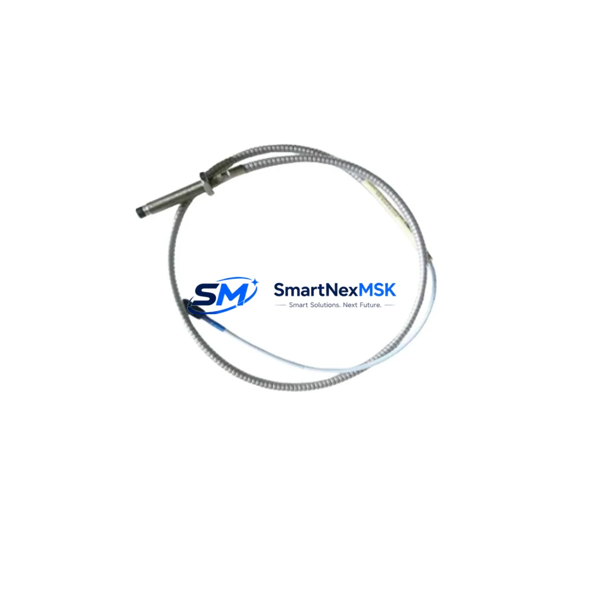
Bently Nevada 330500-00-01 Maintenance-Ready Spare for 3300 Series Automation
The Bently Nevada 330500-00-01 Velomitor Piezo-Velocity Sensor is a precision industrial spare component engineered for continuous vibration monitoring in rotating machinery applications. Designed to integrate seamlessly with Bently Nevada 3300 Series monitoring systems, this sensor delivers reliable velocity output signals critical for detecting imbalance, misalignment, looseness, and bearing wear in turbines, compressors, pumps, and motors. For maintenance engineers managing aging control infrastructure or executing planned overhauls, having a verified, tested replacement unit on the shelf is the single most effective strategy for minimizing unplanned downtime.
Industrial facilities operating Bently Nevada 3300 Series machinery protection systems depend on the 330500-00-01 as a front-line sensing element. When this sensor degrades or fails, the entire vibration monitoring loop is compromised — leaving rotating equipment unprotected and exposing the plant to catastrophic mechanical failure. Procurement engineers sourcing this part should treat it as a critical-path spare, not a commodity item. Our stock is sourced from authorized supply chains, individually tested prior to shipment, and backed by a 12-month warranty covering manufacturing defects and functional performance.
Spare Maintenance Table
| Parameter | Specification |
|---|---|
| Part Number | 330500-00-01 |
| Brand | Bently Nevada |
| Series Compatibility | 3300 Series Machinery Protection System |
| Sensor Type | Velomitor Piezo-Velocity Sensor |
| Output Signal | Velocity (mV/mm/s or mV/in/s) |
| Frequency Range | 2 Hz – 1000 Hz |
| Operating Temperature | -40°C to +121°C |
| Housing Material | Stainless Steel |
| Connector Type | 2-pin MIL-C-5015 style |
| Mounting | Stud mount, side-exit cable |
| Application Environment | Turbines, Compressors, Pumps, Motors, Fans |
| Maintenance Recommendation | Replace at first sign of signal drift, noise floor increase, or physical damage to cable/connector |
| Warranty | 12 Months from date of shipment |
| Pre-shipment Testing | Functional output verification, insulation resistance check |
| Origin | United States |
Maintenance Planning for Continuous Operation
When a 330500-00-01 Velomitor sensor is flagged for replacement during a scheduled outage or emergency shutdown, experienced maintenance engineers know that the sensor itself is rarely the only component requiring attention. A thorough inspection of the associated monitoring loop is essential to restore full system integrity and prevent repeat failures.
Begin by inspecting the 330130-080-00-05 extension cable or equivalent field wiring between the sensor and the 3300 Series monitor rack — cable insulation breakdown and connector corrosion are leading causes of false alarms and signal loss. At the rack level, verify the condition of the 3300/16 Dual Voting Logic Monitor or 3300/20 Radial Vibration Monitor input card, as a degraded sensor can mask underlying card faults that only become apparent after the sensor is replaced. Check the 3300/55 Power Supply module for output voltage stability; a sagging supply rail will affect sensor bias and signal accuracy across all channels simultaneously.
For facilities running integrated condition monitoring, the 3500/42M Proximitor/Seismic Monitor and 3500/45 Position Monitor modules in adjacent rack slots should be inspected for alarm setpoint drift and relay output integrity. If the plant uses a Bently Nevada TDXnet Data Acquisition Module or System 1 Condition Monitoring Software interface, confirm that the replacement sensor’s calibration data is correctly entered to avoid false baseline deviations.
On the field side, inspect the junction box terminal blocks and cable gland seals for moisture ingress — a common failure mode in outdoor or wash-down environments. If the machinery is also equipped with proximity probes for shaft displacement monitoring, cross-check the 330180-91-00 Proximity Probe and its associated 330130 extension cable for wear, as velocity and displacement sensors are often replaced as a pair during major overhauls. Finally, verify that the Keyphasor module signal is clean and phase-referenced correctly, as a corrupted Keyphasor input will invalidate all synchronous vibration analysis derived from the new sensor’s output.
Site Replacement Workflow
Replacing the 330500-00-01 in the field follows a structured sequence designed to minimize exposure time and confirm system restoration before returning the machine to service:
1. Pre-replacement verification: Confirm the replacement unit’s part number, revision level, and sensitivity rating match the installed sensor’s dataplate. Cross-reference with the 3300 Series monitor’s channel configuration to ensure the input scaling is compatible. Do not assume all 330500-series variants are interchangeable without checking the suffix code.
2. Safe isolation: Follow site LOTO (Lockout/Tagout) procedures. Disconnect the sensor cable at the junction box before removing the sensor body from the machinery casing. Avoid pulling on the cable — use the connector body to disengage.
3. Physical installation: Clean the mounting surface and inspect the stud thread for corrosion or damage. Apply appropriate anti-seize compound if specified by site procedures. Torque the sensor to the manufacturer’s specification. Route the cable to avoid contact with hot surfaces, sharp edges, or high-voltage conduit.
4. Signal verification: After reconnection, power up the monitoring channel and verify the bias voltage at the monitor input card is within the specified range (typically -8 to -12 VDC for Velomitor-type sensors). Confirm the vibration reading is within expected baseline range for the machine at normal operating speed before releasing the bypass.
5. Documentation: Record the replacement in the plant CMMS with the new sensor’s serial number, installation date, and post-replacement baseline readings. This data is essential for trending and future maintenance planning.
This workflow applies equally to planned maintenance windows and emergency replacements, and is designed to keep total downtime under four hours for a single-channel sensor swap on accessible machinery.
Spare Parts Support FAQ
Q: Is the 330500-00-01 still in production, or is this an end-of-life part?
A: Bently Nevada has transitioned some 3300 Series components to the 3500 Series platform, but the 330500-00-01 remains available as an original spare for installed base support. We maintain stock specifically to support facilities that cannot justify a full system upgrade. Contact us to confirm current availability and lead time.
Q: How do I verify compatibility before ordering?
A: Confirm the monitor model number (e.g., 3300/16, 3300/20) and the existing sensor’s part number suffix. The 330500-00-01 is compatible with standard 3300 Series velocity input channels. If your system uses a non-standard input card or a third-party DCS interface, provide the monitor datasheet and we will confirm compatibility before shipment.
Q: What testing is performed before shipment?
A: Each unit undergoes functional output verification under simulated vibration input, insulation resistance testing between signal conductors and housing, and connector integrity inspection. A test report is available upon request. Units that do not meet Bently Nevada’s original performance specifications are not shipped.
Q: What does the 12-month warranty cover?
A: The warranty covers manufacturing defects, functional performance failure under normal operating conditions, and connector/cable integrity for the sensor body. It does not cover damage resulting from improper installation, overvoltage, mechanical impact, or exposure to conditions outside the rated operating envelope. Warranty claims are processed with return shipment and replacement dispatch within 5 business days of receipt.
© 2026 SMARTNEXMSK. All rights reserved.
Original Source: https://smartnexmsk.com
Contact: [email protected] | +86 18259474341



