
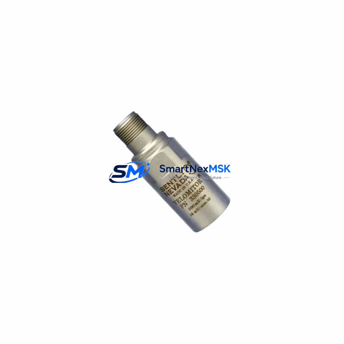
Bently Nevada 330500-04-00 Spare for 3300 Automation: Spare Replacement & Industrial Downtime Risk Control
The Bently Nevada 330500-04-00 Velomitor® Piezo-Velocity Sensor is a precision industrial spare component designed for continuous machinery protection in rotating equipment monitoring systems. As part of the Bently Nevada 3300 Series platform, this sensor delivers reliable velocity measurement for turbines, compressors, pumps, motors, and other critical rotating assets where unplanned downtime carries significant operational and financial risk.
For maintenance engineers managing aging control infrastructure, the 330500-04-00 represents a direct, specification-matched replacement for worn or failed Velomitor sensors. Its piezo-velocity measurement principle provides a wide frequency response range, making it suitable for both low-speed and high-speed machinery protection applications. Procurement engineers sourcing spare parts for planned shutdowns or emergency replacements can rely on this unit as a verified OEM-equivalent component with full compatibility confirmation against the 3300 Series monitor rack.
Every unit shipped from SMARTNEXMSK undergoes pre-shipment functional verification, including output signal integrity checks and connector inspection. Stock is maintained for rapid dispatch to minimize mean time to repair (MTTR) in critical plant environments. A 12-month warranty covers all units against manufacturing defects, providing assurance for both planned maintenance budgets and emergency procurement scenarios.
Spare Maintenance Table
| Parameter | Specification |
|---|---|
| SKU / Part Number | 330500-04-00 |
| Brand | Bently Nevada |
| Series | 3300 Series |
| Product Type | Velomitor® Piezo-Velocity Sensor |
| Measurement Type | Velocity (piezoelectric) |
| Output Signal | Voltage (mV/mm/s or mV/in/s) |
| Frequency Response | Approx. 2 Hz – 2,000 Hz (–3 dB) |
| Operating Temperature | –40°C to +121°C (–40°F to +250°F) |
| Connector Type | 2-pin MIL-C-5015 style |
| Housing Material | Stainless steel |
| Mounting | Threaded stud, side or top exit |
| Compatibility | Bently Nevada 3300 Series monitor racks; 3500 Series (with adapter) |
| Application Environment | Turbines, compressors, pumps, motors, gearboxes |
| Ingress Protection | IP67 (sealed housing) |
| Origin | USA |
| Warranty | 12 Months |
| Pre-Shipment Test | Signal output verification, connector integrity check |
| Lead Time | In stock — ships within 1–3 business days |
Maintenance Planning for Continuous Operation
When replacing the 330500-04-00 Velomitor sensor during a scheduled outage or emergency callout, a thorough inspection of the surrounding measurement chain is essential to prevent repeat failures and ensure system integrity. Maintenance engineers should treat sensor replacement as an opportunity to audit the full vibration monitoring loop.
Begin by inspecting the Bently Nevada 330130-080-00-00 interconnect cable or equivalent field wiring between the sensor and the monitor rack. Cable insulation degradation, connector corrosion, or shield continuity faults are common root causes of spurious vibration alarms that are often misattributed to sensor failure. Verify cable continuity and insulation resistance before reinstalling.
At the monitor rack, confirm that the associated Bently Nevada 3300/16-02-01-00 Velomitor Input Module is functioning correctly. Input modules can develop channel-specific faults that mimic sensor failures; swapping the sensor without verifying the module may result in a repeat fault condition. Check the module’s OK relay output and channel status LEDs.
Review the 3300/05 Power Supply Module supplying the monitor rack. Voltage sag or ripple on the 24 VDC rail can cause erratic sensor output and false trip events. Use a calibrated multimeter or oscilloscope to verify supply stability under load. If the power supply is approaching its rated service life, include it in the planned replacement schedule.
For systems integrated with a Bently Nevada 3500 Series rack via a gateway or legacy interface, verify that the communication module — such as the 3500/92 Communication Gateway — is correctly configured for the sensor type and that alarm setpoints have been updated to reflect the replacement unit’s sensitivity specification.
Inspect the terminal blocks and field junction boxes associated with the sensor wiring. Loose terminations, oxidized contacts, or incorrect torque on screw terminals are frequent contributors to intermittent signal faults in high-vibration environments. Re-torque all terminations to specification and apply contact enhancer where appropriate.
If the plant uses a DCS historian or SCADA system — such as an Emerson DeltaV or Honeywell Experion integration — confirm that the new sensor’s tag configuration and engineering unit scaling are correctly mapped after replacement. Misconfigured scaling can result in out-of-range readings that trigger unnecessary shutdowns.
For facilities maintaining a spare parts inventory for rotating equipment protection, it is recommended to stock at minimum one additional 330500-04-00 unit alongside compatible proximity probe extension cables (330130 series), a spare Velomitor input module, and a set of 3300 Series barrier isolators or signal conditioners to support rapid swap-out during unplanned outages. Maintaining a documented bill of materials (BOM) for each monitor rack cabinet significantly reduces diagnostic time during emergency maintenance.
Site Replacement Workflow
Step 1 — Isolation & Lockout/Tagout: Follow site LOTO procedures. Isolate the monitor channel at the rack before disconnecting the sensor. Note the current alarm and danger setpoints for the channel.
Step 2 — Sensor Removal: Disconnect the field cable at the sensor connector. Remove the sensor from its mounting stud, noting the orientation and any sealant or thread compound used. Inspect the mounting surface for corrosion or mechanical damage.
Step 3 — Compatibility Verification: Confirm the replacement 330500-04-00 unit matches the original in sensitivity (mV/mm/s), connector type, and cable exit direction. Cross-reference the unit’s label against the monitor rack’s channel configuration sheet.
Step 4 — Installation: Apply appropriate thread sealant to the mounting stud. Torque the sensor to the manufacturer’s specification. Reconnect the field cable, ensuring the connector is fully seated and the locking ring is engaged.
Step 5 — Functional Verification: Restore power to the monitor channel. Verify the OK status LED on the input module illuminates. Confirm the live vibration reading is within the expected baseline range for the machine at its normal operating speed. Compare against historical trend data if available.
Step 6 — Documentation: Record the replacement in the plant maintenance management system (CMMS), including the new unit’s serial number, installation date, and post-installation readings. Update the spare parts inventory to trigger reorder of the consumed unit.
This workflow supports a like-for-like replacement that maintains system compatibility, preserves alarm setpoint integrity, and minimizes the risk of introducing new faults during the maintenance intervention. The 330500-04-00 is a direct replacement for legacy Velomitor units in the 3300 Series platform, requiring no firmware changes or rack reconfiguration in standard installations.
Spare Parts Support FAQ
Q1: What is the service life expectation for the 330500-04-00, and when should it be scheduled for replacement?
The Bently Nevada 330500-04-00 Velomitor sensor is designed for long-term continuous service in industrial environments. In practice, sensors installed in high-temperature or high-vibration locations may exhibit sensitivity drift after 5–10 years of service. It is recommended to include Velomitor sensors in the plant’s periodic calibration and condition assessment schedule, replacing units that show sensitivity deviation beyond ±10% of the original specification or that exhibit intermittent OK faults. Proactive replacement during planned shutdowns is significantly less costly than emergency replacement during an unplanned trip.
Q2: How do I verify compatibility before installation in an existing 3300 Series rack?
Compatibility verification involves three checks: (1) confirm the monitor rack’s input module is configured for Velomitor-type sensors (not proximity probe or accelerometer inputs); (2) verify the cable connector type matches the 330500-04-00’s 2-pin MIL-C-5015 style; and (3) confirm the channel’s sensitivity scaling in the monitor configuration matches the sensor’s rated output (typically 100 mV/in/s or 4 mV/mm/s). SMARTNEXMSK can provide technical support for compatibility confirmation prior to order placement.
Q3: What pre-shipment testing is performed on each unit, and what does the 12-month warranty cover?
Each 330500-04-00 unit undergoes output signal verification and connector integrity inspection before dispatch. The 12-month warranty covers manufacturing defects, including sensor element failure, connector faults, and housing integrity issues under normal operating conditions. Warranty claims are supported by SMARTNEXMSK’s technical team with replacement or repair at no additional cost. Units damaged by installation errors, overvoltage, or mechanical impact are assessed on a case-by-case basis.
Q4: Can SMARTNEXMSK support long-term or blanket purchase orders for ongoing spare parts inventory programs?
Yes. SMARTNEXMSK supports B2B procurement programs including blanket purchase orders, scheduled releases, and consignment stock arrangements for high-usage spare parts. For facilities managing multiple 3300 Series racks or operating large rotating equipment fleets, a dedicated spare parts supply agreement ensures priority stock allocation and agreed lead times. Contact our sales team to discuss volume pricing and supply program options.
© 2026 SMARTNEXMSK. All rights reserved.
Original Source: https://smartnexmsk.com
Contact: [email protected] | +86 18259474341



