
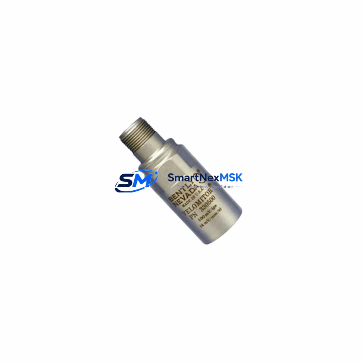
Bently Nevada 330500-07-00 Retrofit-Ready Piezo-Velocity Sensor for Velomitor XA Control Systems
The Bently Nevada 330500-07-00 is a high-performance piezo-velocity sensor engineered for the Velomitor XA series, widely deployed in rotating machinery protection and condition monitoring systems across oil & gas, power generation, petrochemical, and heavy industrial facilities. As legacy Velomitor sensor variants approach end-of-life or become increasingly difficult to source, the 330500-07-00 serves as the authoritative retrofit-ready replacement — delivering full signal compatibility, identical connector pinout, and equivalent frequency response characteristics without requiring modifications to existing wiring harnesses or monitor configurations.
This sensor integrates directly with Bently Nevada 3500 Series machinery protection systems, including the 3500/42M Proximitor/Seismic Monitor and the 3500/45 Position Monitor, both of which are commonly found in turbine, compressor, and pump protection panels. Engineers migrating from older 330500-00-00 or 330500-05-00 variants will find the 330500-07-00 electrically and mechanically interchangeable, significantly reducing retrofit engineering time and eliminating the need for I/O reconfiguration at the monitor card level.
For facilities operating System 1 or System 1 Evolution condition monitoring software, the 330500-07-00 maintains full data integrity across existing trend archives and alarm setpoints. No software reconfiguration is required at the Bently Nevada TDI (Transient Data Interface) or Data Manager level, preserving historical vibration baselines critical for predictive maintenance programs.
Upgrade Compatibility Table
| Parameter | Details |
|---|---|
| SKU / Part Number | 330500-07-00 |
| Brand / Manufacturer | Bently Nevada (Baker Hughes) |
| Series | Velomitor XA Piezo-Velocity Sensor |
| Replaces / Supersedes | 330500-00-00, 330500-05-00, 330500-06-00 |
| Compatible Monitor Cards | 3500/42M, 3500/45, 3500/40M |
| Connector / Interface | 2-pin MIL-C-5015 style, drop-in compatible |
| Frequency Response | 4.5 Hz – 5,000 Hz (±3 dB) |
| Output Sensitivity | 100 mV/in/s (4 mV/mm/s) |
| Power Supply | 18–30 VDC (supplied via monitor card) |
| Installation | Stud-mount, ¼-28 UNF thread; no backplate modification required |
| Communication Compatibility | Analog 4–20 mA / voltage output; compatible with 3500 rack I/O |
| Commissioning Notes | Verify OK voltage (10–14 VDC), check gap voltage, confirm alarm setpoints in monitor |
| Warranty | 12 Months from date of shipment |
Retrofit Planning for Existing Automation Systems
Successful integration of the 330500-07-00 into an existing machinery protection panel begins with a thorough review of the current rack configuration. Most 3500 Series installations pair the Velomitor XA sensor with a 3500/20 Rack Interface Module (RIM) and a 3500/15 Power Supply — both of which should be inspected for output voltage stability before sensor replacement. A degraded power supply delivering less than 18 VDC will cause the replacement sensor to report a false “not OK” condition, which is frequently misdiagnosed as a faulty sensor during commissioning.
Terminal wiring for the 330500-07-00 follows the standard Velomitor XA two-wire configuration: Signal (white) and Shield/Return (bare). Engineers should verify continuity and insulation resistance on the existing field cable before reuse — particularly in installations where the cable has been routed through high-temperature zones adjacent to turbine casings or steam lines. Where cable replacement is necessary, Bently Nevada 330130-080-00 or equivalent armored extension cable is recommended to maintain signal integrity over long cable runs.
For facilities upgrading from a legacy Bently Nevada 7200 Series or 3300 Series monitoring system to the 3500 platform, the retrofit scope expands significantly. The 3500/22M Transient Data Interface and 3500/32 4-Channel Relay Module will need to be configured to match the new sensor’s output characteristics. I/O mapping in the 3500 Rack Configuration Software (RCS) must be updated to reflect the new channel assignments, and any existing Modbus RTU or FOUNDATION Fieldbus communication links to the plant DCS should be re-verified after rack reconfiguration.
HMI screens connected to the machinery protection system — whether running on GE iFIX, Wonderware InTouch, or a proprietary SCADA platform — should be reviewed to confirm that tag names, engineering unit scaling, and alarm display logic remain consistent after the sensor swap. In most cases, no HMI modification is required for a like-for-like Velomitor XA replacement, but a full-load functional test should be conducted before returning the machine to service.
Downtime Control During System Migration
Minimizing unplanned downtime during a Velomitor XA sensor replacement requires a structured pre-outage preparation protocol. Before the maintenance window opens, engineers should download and archive the current 3500 RCS configuration file and export all active alarm setpoints, OK limits, and transducer scale factors. This backup ensures that if the replacement sensor requires any monitor-level adjustment, the original parameters can be restored within minutes rather than hours.
During the physical swap, the machine should be in a controlled shutdown state with the 3500/15 Power Supply de-energized at the rack level — not simply bypassed at the field junction box. This prevents residual voltage from appearing on the sensor terminals during installation, which can damage the piezo element in the new 330500-07-00. Once the sensor is installed and the terminal connections are torqued to specification, re-energize the rack and confirm the OK LED status on the 3500/42M monitor card before proceeding to alarm verification.
For critical machinery where continuous monitoring is contractually required, a temporary portable vibration analyzer — such as a CSI 2140 or equivalent — can be connected to the machine casing during the sensor swap interval to maintain vibration surveillance. This approach is particularly valuable in combined-cycle power plants where turbine protection cannot be fully bypassed without triggering a unit trip. Once the 330500-07-00 is confirmed operational and all setpoints are verified, the portable analyzer can be removed and the permanent protection system restored to service.
All commissioning results — including OK voltage readings, gap voltage measurements, and alarm trip test records — should be documented in the plant maintenance management system (CMMS) and attached to the equipment history file for the monitored machine. This documentation supports future audits, insurance reviews, and reliability engineering analysis.
Retrofit Support FAQ
Q1: Is the 330500-07-00 a direct drop-in replacement for the 330500-05-00 and 330500-06-00?
Yes. The 330500-07-00 is the current production revision of the Velomitor XA sensor family and is electrically, mechanically, and functionally interchangeable with the 330500-05-00 and 330500-06-00. No changes to monitor card configuration, wiring, or software setpoints are required for a direct swap. Confirm OK voltage (10–14 VDC) after installation as a standard commissioning check.
Q2: What wiring checks should be performed before installing the replacement sensor?
Verify that the existing field cable has no shorts between Signal and Shield conductors, and that insulation resistance exceeds 100 MΩ at 500 VDC. Check that the cable shield is grounded at one end only (typically at the monitor card end) to prevent ground loops. Inspect the MIL-C-5015 connector backshell for corrosion or moisture ingress, and replace the connector if any contamination is found.
Q3: Will the 330500-07-00 work with our existing Modbus or FOUNDATION Fieldbus DCS integration?
The 330500-07-00 itself is an analog sensor; communication to the DCS is handled by the 3500 Series monitor card and rack interface module. Replacing the sensor does not affect the Modbus RTU or FOUNDATION Fieldbus communication link between the 3500 rack and the DCS. However, after any rack reconfiguration, it is good practice to perform a full communication health check and verify that all process variables are being correctly received at the DCS historian.
Q4: What does the 12-month warranty cover, and what is the return process?
All 330500-07-00 units supplied by SMARTNEXMSK carry a 12-month warranty from the date of shipment, covering manufacturing defects and functional failures under normal operating conditions. Units that fail within the warranty period should be returned with a completed failure description form. Upon receipt and inspection, a replacement unit will be dispatched within 5 business days. Warranty does not cover damage resulting from incorrect installation, overvoltage, or physical impact.
© 2026 SMARTNEXMSK. All rights reserved.
Original Source: https://smartnexmsk.com
Contact: [email protected] | +86 18259474341



