
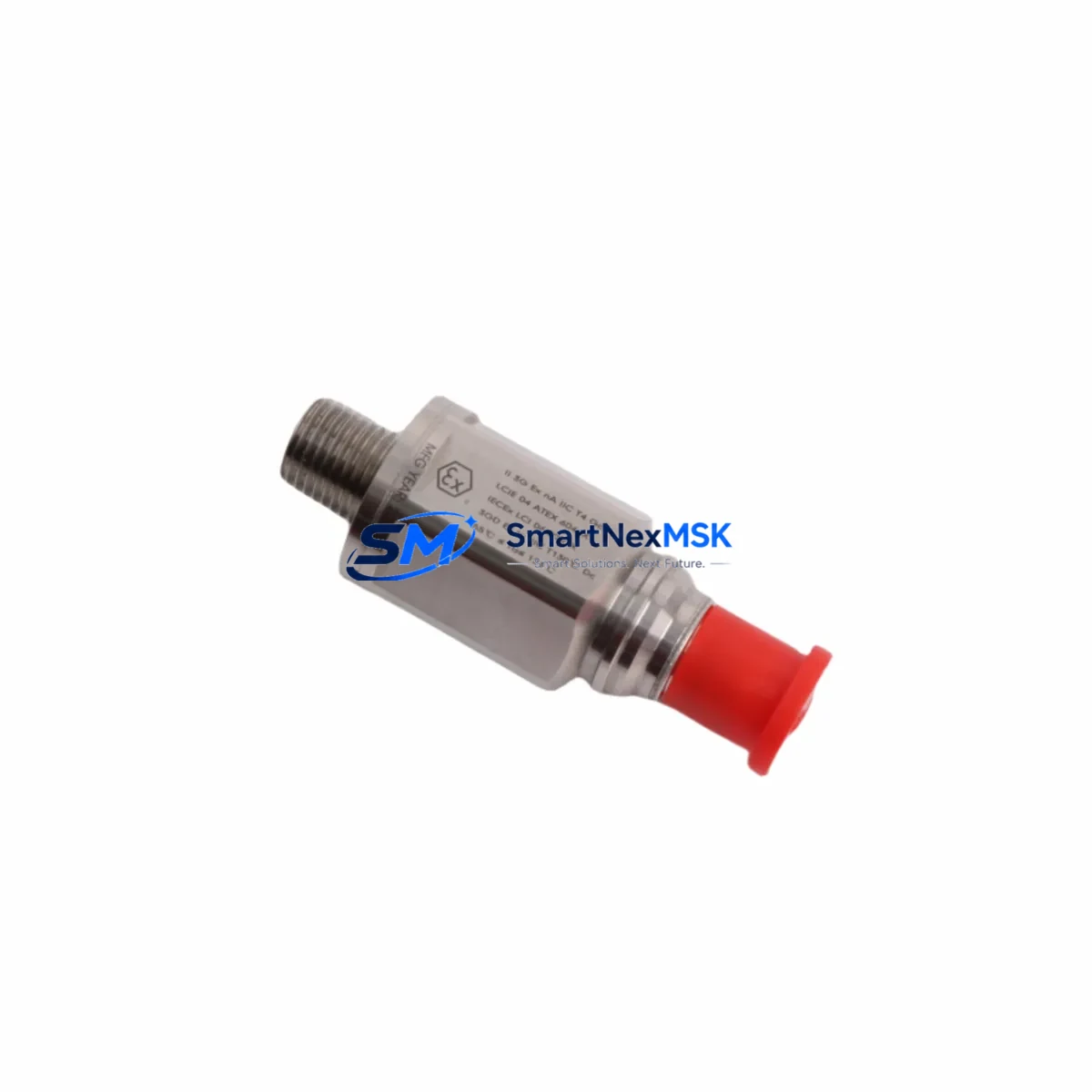
Bently Nevada 330525-00 Spare for Velomitor XA Automation
The Bently Nevada 330525-00 Velomitor XA Piezo-Velocity Vibration Sensor is a precision-engineered original spare part designed for continuous vibration monitoring in rotating machinery and critical industrial automation systems. Engineered to integrate seamlessly with Bently Nevada 3300 and 3500 Series monitoring platforms, this sensor delivers reliable velocity output signals essential for early fault detection, bearing wear analysis, and unbalance identification in turbines, compressors, pumps, and motors.
For maintenance engineers managing aging control infrastructure, sourcing a verified original 330525-00 is the fastest path to restoring full condition monitoring capability after sensor failure. Unlike generic substitutes, the 330525-00 maintains the calibrated sensitivity and frequency response required by the 3300 and 3500 rack systems, ensuring alarm setpoints and trip thresholds remain accurate without recalibration. Every unit is function-tested prior to shipment and backed by a 12-month warranty covering manufacturing defects and performance deviations.
Procurement engineers will find long-term supply continuity a key advantage: the 330525-00 is stocked as a standard line item, available for immediate dispatch with full documentation including calibration records and conformance certificates on request.
Spare Maintenance Table
| Parameter | Specification |
|---|---|
| Part Number | 330525-00 |
| Brand | Bently Nevada |
| Series | Velomitor XA |
| Sensor Type | Piezo-Velocity Vibration Sensor |
| Output Signal | Velocity (mV/mm/s or mV/in/s) |
| Frequency Range | Approx. 2 Hz – 2,000 Hz |
| Compatible Systems | Bently Nevada 3300 Series, 3500 Series Monitoring Racks |
| Mounting | Stud mount, radial or axial orientation |
| Operating Temperature | -40°C to +121°C |
| Ingress Protection | IP67 (sealed, suitable for wet/oily environments) |
| Connector Type | 2-pin MIL-spec connector |
| Origin | USA |
| Condition | Original New / Surplus New |
| Warranty | 12 Months from date of shipment |
| Pre-shipment Test | Function tested, output verified |
| Documentation | Calibration record & conformance certificate available on request |
| Lead Time | In stock — ships within 1–3 business days |
Maintenance Planning for Continuous Operation
When a 330525-00 Velomitor XA sensor is flagged for replacement during a scheduled outage or emergency shutdown, experienced maintenance engineers know that the sensor itself is rarely the only component requiring attention. A thorough inspection of the surrounding measurement loop and monitoring rack is essential to prevent repeat failures and ensure the restored system meets its original design intent.
Begin with the sensor interconnect cable — the Bently Nevada 330130-xx or 330180-xx armored extension cables are the most common field-replaceable items in this loop. Cable jacket cracking, connector corrosion, and shield continuity breaks are frequent causes of noisy or lost vibration signals that are misdiagnosed as sensor failure. Inspect the full cable run from the sensor to the junction box.
At the 3500/42M Proximitor/Seismic Monitor or 3300/16 Velocity Monitor module level, verify that the input channel is reading within expected mV/EU range after sensor swap. If the channel shows drift or alarm hysteresis issues, the monitor module itself may require recalibration or replacement — the 3500/42M and 3300/16 are standard stocked modules for this reason.
Check the 3500/01 Rack Power Supply output voltage stability. A degraded rack power supply can introduce ripple into sensor excitation circuits, producing false vibration readings that persist even after a sensor replacement. The 3500/05 System Monitor module provides rack-level diagnostics and should be reviewed for any latched fault codes before returning the system to service.
For systems using Keyphasor® probes (such as the 330980-xx series) in the same machinery train, confirm that the Keyphasor signal is clean and phase-stable — a degraded Keyphasor reference will corrupt vector-based vibration analysis even with a new 330525-00 installed. Similarly, inspect proximity probe drivers (3300 XL 8mm or 11mm probes with 3300/05 drivers) on the same shaft for gap voltage compliance.
In the control cabinet, verify terminal block torque values on the signal wiring terminations. Loose terminations on DIN-rail mounted terminal strips are a leading cause of intermittent vibration channel faults in high-vibration environments. If the cabinet houses a Bently Nevada 3500/22M Transient Data Interface, confirm that the TDI firmware is current and that the channel mapping reflects the new sensor installation.
For plants running System 1 Evolution condition monitoring software, update the sensor configuration database to reflect the replacement date and new serial number. This ensures that baseline trending data is correctly segmented and that alarm rationalization reviews use accurate historical context.
Site Replacement Workflow
Step 1 — Isolation & Lockout: Follow site LOTO procedures. Isolate the vibration monitoring channel at the 3500 or 3300 rack. Note the current gap voltage and vibration reading for the channel being replaced.
Step 2 — Sensor Removal: Disconnect the extension cable at the sensor connector. Remove the 330525-00 from its mounting stud. Inspect the mounting surface for corrosion, thread damage, or contamination that could affect the new sensor’s mechanical coupling.
Step 3 — New Sensor Installation: Install the replacement 330525-00 to the manufacturer’s specified torque. Reconnect the extension cable, ensuring the connector is fully seated and the locking ring is secure. Verify cable routing avoids heat sources and mechanical contact points.
Step 4 — Channel Verification: Restore power to the monitoring channel. Confirm the output signal is within the expected velocity range for the machine’s normal operating state. Check that no alarms are latched in the 3500/05 System Monitor.
Step 5 — Documentation: Record the replacement in the plant CMMS (SAP PM, Maximo, or equivalent). Log the new sensor serial number, installation date, and post-replacement readings. Update the System 1 sensor database if applicable.
This workflow minimizes downtime, maintains system compatibility, and creates a traceable maintenance record that supports future reliability analysis and spare parts planning.
Spare Parts Support FAQ
Q1: Is the 330525-00 compatible with both the 3300 and 3500 Series monitoring racks?
Yes. The Velomitor XA 330525-00 is designed to interface with Bently Nevada 3300 Series and 3500 Series velocity monitoring modules. Always verify the specific monitor module’s input impedance and signal conditioning requirements against the sensor datasheet before installation in non-standard configurations.
Q2: What testing is performed before shipment?
Each 330525-00 unit undergoes functional output verification prior to dispatch. Calibration records and conformance certificates are available on request. Units are packaged in anti-static, shock-protected packaging to prevent transit damage.
Q3: How should the 330525-00 be stored if not immediately installed?
Store in a dry, temperature-controlled environment (10°C–35°C) away from strong magnetic fields and vibration sources. Keep in original packaging with desiccant. Recommended maximum storage period before installation inspection is 24 months.
Q4: What does the 12-month warranty cover?
The 12-month warranty covers manufacturing defects and performance deviations from published specifications under normal operating conditions. It does not cover damage resulting from incorrect installation, overvoltage, mechanical impact, or operation outside the rated environmental envelope. Warranty claims are supported with replacement or full refund at our discretion.
© 2026 SMARTNEXMSK. All rights reserved.
Original Source: https://smartnexmsk.com
Contact: [email protected] | +86 18259474341



