
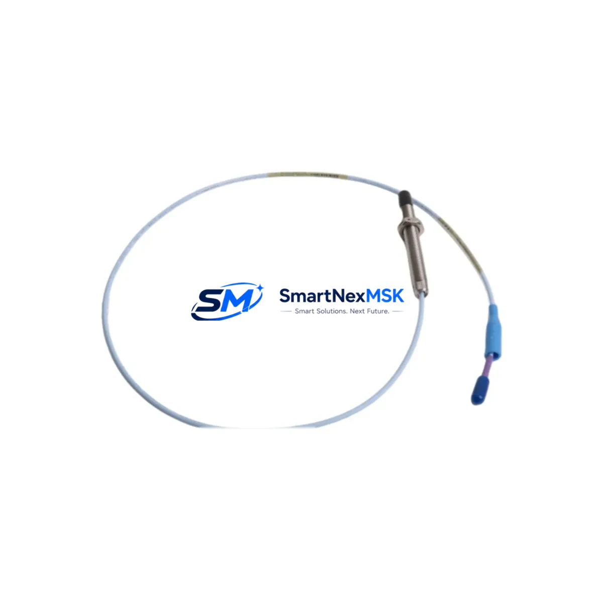
Bently Nevada 330701-00-40-10-02-05 Retrofit-Ready Proximity Transducer for 3300 XL Control Systems
The Bently Nevada 330701-00-40-10-02-05 is a high-precision eddy-current proximity transducer engineered for the 3300 XL Series condition monitoring platform. As legacy 3300 Series installations approach end-of-life and OEM support windows close, plant engineers and reliability teams increasingly require a verified, drop-in retrofit solution that preserves existing wiring infrastructure, maintains signal chain integrity, and eliminates the need for full rack replacement. The 330701-00-40-10-02-05 addresses exactly this requirement — delivering a smooth migration path from discontinued proximity transducer assemblies to a fully supported, field-proven replacement with a 12-month warranty and pre-shipment functional testing.
This transducer is designed for radial and axial shaft vibration measurement on rotating machinery including steam turbines, gas compressors, centrifugal pumps, and large induction motors. It operates within the standard Bently Nevada 3300 XL signal conditioning architecture, making it directly compatible with the 3300/16 XL monitor, the 3300/20 XL monitor, and associated I/O terminal blocks. Engineers retrofitting from the earlier 330700 or 330180 series will find that the 330701-00-40-10-02-05 maintains the same 8 mm probe diameter, -24 VDC bias voltage, and 200 mV/mil (7.87 V/mm) scale factor, eliminating the need to recalibrate monitor setpoints or modify existing Proximitor® extension cable runs.
When planning a retrofit around the 330701-00-40-10-02-05, the following verification steps are critical to a successful cutover:
- Power Supply Capacity: Confirm that the rack power supply — typically the Bently Nevada 3300/05 Power Supply module — can sustain the additional current draw if multiple transducers are being replaced simultaneously. A single 330701-00-40-10-02-05 draws approximately 12 mA; verify total channel loading against the supply’s rated output before energizing.
- Terminal Wiring: The transducer uses a standard coaxial connector at the probe tip and a 3-pin MIL-spec connector at the Proximitor® driver. Confirm that existing extension cables — such as the 330130 or 330180 series extension cables — are within their rated length and show no shield continuity faults before reconnecting.
- Backplane Interface: In 3300 XL racks, the monitor card interfaces with the backplane via a dedicated I/O module. Ensure the 3300/16 XL or 3300/20 XL monitor card firmware is at a revision level that supports the 330701 transducer family. Older firmware revisions may require an update via the System 1 configuration software before the new transducer is recognized correctly.
- Module Addressing: Each channel in the 3300 XL rack is addressed by slot position. After physical installation, verify channel address assignments in System 1 Evolution or System 1 Classic match the physical slot of the replaced transducer to avoid alarm misrouting.
- Program Compatibility: If the plant DCS — such as a Honeywell Experion PKS, Emerson DeltaV, or ABB 800xA system — receives vibration data from the 3300 XL rack via a Modbus RTU or OPC DA gateway, confirm that the data register map remains unchanged after the transducer swap. No re-mapping is typically required for a like-for-like 330701 replacement, but this should be verified against the existing I/O list.
- HMI Screen Validation: After cutover, validate that the plant HMI — whether a Wonderware InTouch, iFIX, or Ignition SCADA screen — displays correct gap voltage, vibration amplitude, and alarm status for the replaced channel. A gap voltage reading of -10 VDC ±0.5 V at the nominal air gap confirms correct installation.
- Communication Link Integrity: If the 3300 XL rack communicates with a plant historian or condition monitoring server via a 3500/92 Ethernet I/O Module or a dedicated Modbus TCP gateway, verify that the communication link remains active and that no watchdog timeouts occur after the transducer replacement.
- Field Commissioning: Perform a slow-roll vibration check at shaft speeds below 600 RPM to confirm baseline gap voltage and noise floor before returning the machine to full-speed operation. Document the as-found and as-left gap voltage readings for the maintenance record.
Upgrade Compatibility Table
| Parameter | 330701-00-40-10-02-05 (This Unit) | Legacy 330700 / 330180 Series | Retrofit Notes |
|---|---|---|---|
| Probe Diameter | 8 mm | 8 mm | No bore modification required |
| Scale Factor | 200 mV/mil (7.87 V/mm) | 200 mV/mil | Monitor setpoints unchanged |
| Bias Voltage | -24 VDC nominal | -24 VDC nominal | No power supply adjustment needed |
| Extension Cable | 330130 / 330180 series compatible | 330130 / 330180 series | Reuse existing cable runs |
| Monitor Compatibility | 3300/16 XL, 3300/20 XL | 3300/16, 3300/20 (non-XL) | Firmware update may be required |
| Connector Type | MIL-spec 3-pin | MIL-spec 3-pin | Direct plug-in replacement |
| Communication Protocol | Modbus RTU / OPC DA via rack gateway | Modbus RTU / OPC DA | No register map changes required |
| Installation Standard | API 670 5th Edition | API 670 4th Edition | Verify probe gap per new standard |
| Warranty | 12 Months | OEM support ended | Full replacement coverage included |
| Pre-shipment Test | Yes — functional & dimensional | N/A | Test report available on request |
Retrofit Planning for Existing Automation Systems
A successful retrofit of the 330701-00-40-10-02-05 into an operating plant environment requires coordinated planning across instrumentation, controls, and operations disciplines. The transducer itself is only one element of the signal chain; the surrounding components must be evaluated in parallel to avoid introducing new failure modes during the cutover window.
Begin by auditing the existing Proximitor® driver — typically a 3300 XL Proximitor® Seismic Transducer assembly mounted in the field junction box adjacent to the machine. If the Proximitor® driver shows signs of moisture ingress, connector corrosion, or output drift, it should be replaced concurrently with the probe to avoid a repeat outage. The 330180-91-00 Proximitor® driver is the standard companion unit for the 330701 probe family and is available from stock.
Next, inspect the extension cable assembly. In many legacy installations, the 330130-080-00-00 or 330130-045-00-00 extension cables have been in service for 10–15 years and may exhibit increased shield resistance or intermittent continuity faults. Replacing the extension cable at the same time as the probe eliminates a common source of post-retrofit noise complaints and avoids a second planned outage.
Within the control cabinet, verify that the 3300/05 Power Supply module is operating within its rated output voltage and current limits. If the rack also houses a 3300/16 XL Dual Voting Logic monitor, a 3300/46 Position monitor, or a 3300/50 Overspeed Detection System, confirm that the total channel count and power draw remain within the rack’s rated capacity after adding the new transducer channel.
For plants where the 3300 XL rack interfaces with a Bently Nevada System 1 condition monitoring server, the System 1 database must be updated to reflect the new transducer serial number and calibration data. This is a software-only change that can be completed without a machine shutdown and typically takes less than 30 minutes for a single channel update.
If the retrofit is part of a broader migration from a legacy 3300 Series rack to a 3500 Series rack — for example, replacing a 3300/16 monitor with a 3500/42M Proximitor® I/O Module — the 330701-00-40-10-02-05 probe remains compatible with the 3500 platform, provided the appropriate 3500/42 I/O module and terminal block are installed. This forward compatibility makes the 330701 a sound investment even for plants planning a phased rack upgrade over a 3–5 year horizon.
Downtime Control During System Migration
Minimizing unplanned downtime is the primary operational constraint in any proximity transducer retrofit. The 330701-00-40-10-02-05 is designed to support a hot-swap replacement strategy where the machine remains online during probe installation preparation, with the actual cutover limited to the time required to de-energize the channel, swap the probe, re-energize, and verify gap voltage — typically 15–30 minutes per channel under normal field conditions.
To protect the original control program logic during the cutover, place the affected monitor channel in bypass mode via the System 1 software or the front-panel keyswitch before disconnecting the probe. This prevents spurious vibration alarms from propagating to the DCS and triggering an unplanned machine trip. Confirm with the control room operator that the bypass is active and logged before proceeding with the physical swap.
Where the plant safety instrumented system (SIS) receives a hardwired trip signal from the 3300 XL rack, coordinate with the SIS engineer to place the relevant SIS input in manual override for the duration of the cutover. Document the override start and end times in the plant management of change (MOC) system.
After reinstalling the 330701-00-40-10-02-05 and verifying gap voltage, perform a channel function test by introducing a known displacement at the probe tip and confirming that the monitor output tracks correctly before removing the bypass. This end-to-end verification — from probe face to DCS display — confirms that the entire signal chain is intact and that the machine can be safely returned to automatic protection.
For multi-channel retrofits involving four or more probes on a single machine train, consider a phased approach: replace radial probes on the drive-end bearing first, verify, then proceed to the non-drive end and thrust position probes. This staged approach limits the number of channels simultaneously in bypass and reduces the risk of a protection gap during the cutover window.
Retrofit Support FAQ
Q1: Is the 330701-00-40-10-02-05 a direct drop-in replacement for the 330700-00-40-10-02-05?
Yes. The 330701-00-40-10-02-05 is dimensionally and electrically compatible with the 330700 series. The probe diameter, thread pitch, scale factor, and bias voltage are identical, allowing direct substitution without modifying the probe holder, extension cable, or monitor setpoints. A gap voltage verification after installation is recommended as standard practice.
Q2: What wiring changes are required when replacing a 330180 series transducer with the 330701-00-40-10-02-05?
No wiring changes are required at the monitor terminal block. The 330701 uses the same 3-pin MIL-spec connector and the same coaxial cable interface as the 330180 series. If the existing extension cable is in good condition, it can be reused. Inspect the cable shield continuity and connector contacts before reconnecting.
Q3: How is the 330701-00-40-10-02-05 tested before shipment?
Each unit undergoes a pre-shipment functional test that verifies scale factor, bias voltage, frequency response, and dimensional conformance to the Bently Nevada specification. A test report is available on request. Units are shipped in anti-static packaging with a calibration label indicating the test date and technician ID. The 12-month warranty period begins from the date of shipment.
Q4: Can the 330701-00-40-10-02-05 be used with a 3500 Series rack as part of a phased upgrade?
Yes. The 330701-00-40-10-02-05 probe is compatible with the Bently Nevada 3500 platform when used with the appropriate 3500/42M Proximitor® I/O Module and the corresponding terminal block. This makes it suitable for plants executing a phased migration from 3300 XL to 3500 Series racks, allowing the probe investment to be retained across both generations of the monitoring platform.
© 2026 SMARTNEXMSK. All rights reserved.
Original Source: https://smartnexmsk.com
Contact: [email protected] | +86 18259474341



