
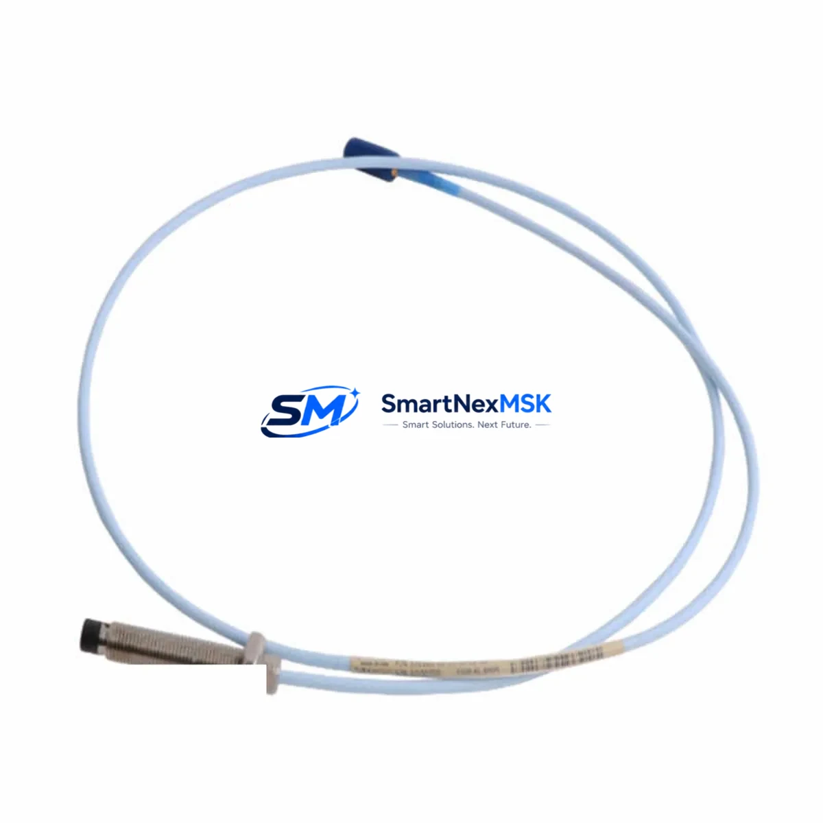
Bently Nevada 330704-000-060-10-02-00 Maintenance-Ready Spare for 3300 XL Automation
The Bently Nevada 330704-000-060-10-02-00 is an original 5mm eddy-current proximity probe assembly designed for the 3300 XL Proximity Transducer System. This component is a critical element in continuous vibration monitoring for rotating machinery — including steam turbines, gas compressors, centrifugal pumps, and large induction motors — where real-time shaft displacement data is essential for predictive maintenance and API 670-compliant protection systems.
Sourced as a genuine OEM spare, this probe assembly is fully compatible with the 3300 XL signal conditioning chain. It is pre-tested prior to shipment, supplied with a 12-month warranty, and available for fast dispatch to minimize unplanned downtime. Whether you are replenishing a critical-spare inventory, replacing a failed probe during a planned outage, or upgrading an aging monitoring loop, this unit delivers the dimensional accuracy and electrical performance required for reliable gap voltage and vibration amplitude readings.
Spare Maintenance Table
| Parameter | Specification |
|---|---|
| Part Number | 330704-000-060-10-02-00 |
| Brand | Bently Nevada |
| Series | 3300 XL Proximity Transducer System |
| Probe Type | 5mm Eddy-Current Proximity Probe |
| Cable Length | 6.0 m (integral cable) |
| Thread Size | M10 × 1.0 (standard 3300 XL mounting) |
| Sensitivity | 7.87 V/mm (200 mV/mil) nominal |
| Linear Range | 0.25 – 2.26 mm (10 – 89 mil) |
| Operating Temperature | −35 °C to +177 °C (probe tip) |
| Target Material Compatibility | AISI 4140 steel (standard); consult datasheet for other alloys |
| System Compatibility | 3300 XL 5mm Extension Cable + 3300 XL Proximitor® Sensor |
| Approvals | CE, ATEX (consult suffix codes for hazardous area ratings) |
| Condition | Original OEM, new or recertified stock |
| Pre-shipment Test | Gap voltage, sensitivity, and insulation resistance verified |
| Warranty | 12 Months |
| Origin | USA |
Maintenance Planning for Continuous Operation
When replacing the 330704-000-060-10-02-00 probe in a 3300 XL monitoring loop, a disciplined maintenance engineer will treat the replacement as an opportunity to inspect the entire transducer chain and associated control-cabinet components. Probe failures rarely occur in isolation — cable degradation, connector corrosion, and Proximitor® sensor drift are common co-failure modes that, if left unaddressed, will cause the new probe to underperform or trigger nuisance trips.
Begin by inspecting the 3300 XL 5mm Extension Cable (e.g., 330130-045-00-00) for jacket cracking, connector pin damage, or moisture ingress at the field-end connector. A degraded extension cable will corrupt the gap voltage reading even with a new probe installed. Next, verify the 3300 XL Proximitor® Sensor (e.g., 330180-X1-05) output voltage at the recommended gap: a reading outside ±0.5 V of the nominal −10 VDC gap voltage indicates sensor drift or power supply deviation.
Check the DC power supply module feeding the Proximitor® — typically a −24 VDC regulated rail. Voltage ripple exceeding 50 mV peak-to-peak can introduce noise into the vibration signal and mask real machinery faults. If the cabinet houses a 3500 series rack or a legacy 3300 rack, inspect the power supply card (e.g., 3500/15 Power Supply) and its fuse holders for signs of thermal stress or intermittent contact.
For I/O integrity, confirm that the 3500/40M Proximitor®/Seismic Monitor or equivalent monitor card is reading the correct OK status and that the channel’s alert and danger setpoints have not drifted from the last calibration record. Relay output modules — such as the 3500/32 Relay Module — should be exercised during the outage window to confirm trip relay coil continuity and contact resistance.
If the machine is part of a DCS-integrated protection loop, verify the 4–20 mA vibration output signal at the DCS I/O card and check the signal isolator or barrier (e.g., a Pepperl+Fuchs KFD2-STV4 signal conditioner or equivalent) for correct scaling. Communication modules linking the 3500 rack to the plant historian or DCS — such as an Ethernet or Modbus gateway card — should be checked for firmware currency and network connectivity.
Finally, review the terminal strip and field wiring inside the junction box at the machine bearing housing. Loose terminations, corroded ferrules, or undersized cable cross-sections are a leading cause of intermittent probe faults that are misdiagnosed as probe failures. Replacing the probe without addressing wiring deficiencies will result in repeat failures and unnecessary spare consumption.
Site Replacement Workflow
Step 1 — Isolation and documentation: Record the existing gap voltage (typically −10 VDC ± 1 V at the recommended air gap) and the current vibration baseline before de-energizing the loop. This baseline is essential for post-installation verification.
Step 2 — Mechanical removal: Using the correct spanner for the M10 × 1.0 thread, back out the probe from the bearing housing bracket. Note the number of turns to reach the original gap setting — this provides a starting reference for the replacement unit. Inspect the bracket threads and probe tip for impact damage or contamination.
Step 3 — Installation of 330704-000-060-10-02-00: Thread the new probe in by hand until snug, then adjust to achieve the target gap voltage (−10.0 VDC ± 0.5 V for standard 4140 steel targets). Lock the probe with the jam nut to the torque specified in the Bently Nevada installation manual. Route the integral cable to avoid sharp bends, heat sources, and high-voltage conductors.
Step 4 — System verification: Re-energize the Proximitor® and confirm OK LED status. Measure gap voltage at the monitor card and compare against the pre-removal baseline. Verify that vibration amplitude readings are consistent with the machine’s known healthy-state signature. Clear any latched alarms and confirm relay outputs have reset.
Step 5 — Documentation and spare replenishment: Update the maintenance record with the new probe serial number, installation date, gap voltage, and technician sign-off. Immediately initiate a purchase order to replenish the consumed spare — maintaining at least one unit of 330704-000-060-10-02-00 per monitored machine in the critical-spare inventory is the recommended practice for facilities operating under continuous-run obligations.
Spare Parts Support FAQ
Q1: Is the 330704-000-060-10-02-00 a direct replacement for older 3300 series probes?
The 330704-000-060-10-02-00 is designed for the 3300 XL system. Compatibility with earlier 3300 (non-XL) probes depends on the Proximitor® sensor variant installed. The 3300 XL Proximitor® sensors are not interchangeable with the original 3300 series sensors. Always confirm the Proximitor® model number before ordering to ensure the probe, extension cable, and sensor are matched as a calibrated system.
Q2: What pre-shipment testing is performed on this probe?
Each unit undergoes gap voltage verification at the nominal air gap, sensitivity measurement (target: 7.87 V/mm ± 10%), and insulation resistance testing between the coil conductors and the probe body. A test certificate is available upon request. Units that do not meet Bently Nevada OEM specifications are not shipped.
Q3: How should this probe be stored in a spare-parts inventory?
Store in the original packaging or an anti-static, moisture-resistant bag in a temperature-controlled environment (0 °C to 40 °C, <85% RH non-condensing). Avoid stacking heavy items on the probe tip or coil housing. Inspect stored units annually for connector corrosion and cable jacket integrity. Recommended maximum shelf life before re-verification is 3 years.
Q4: What is covered under the 12-month warranty?
The 12-month warranty covers manufacturing defects, electrical parameter deviation from OEM specifications, and mechanical integrity of the probe body and integral cable under normal installation and operating conditions. It does not cover damage resulting from incorrect gap setting, mechanical impact, chemical exposure, or installation in systems outside the specified operating parameters. Warranty claims are processed with return of the defective unit and a completed fault report.
© 2026 SMARTNEXMSK. All rights reserved.
Original Source: https://smartnexmsk.com
Contact: [email protected] | +86 18259474341



