
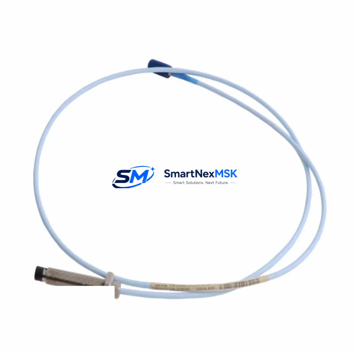
Bently Nevada 330730-040-03-00 Spare for 3300 Automation: Precision Replacement for Continuous Industrial Operation
The Bently Nevada 330730-040-03-00 is a 40-foot (12-metre) armored proximity probe extension cable engineered for the Bently Nevada 3300 Series and fully compatible with the 3500 Series continuous machinery monitoring systems. Designed to transmit low-level eddy-current signals from rotating-shaft proximity probes to their paired proximitor/driver modules, this cable is a critical link in vibration, eccentricity, and axial position measurement loops found in turbines, compressors, pumps, and large rotating machinery across oil & gas, power generation, petrochemical, and heavy manufacturing facilities.
When a proximity probe extension cable degrades — through insulation cracking, connector corrosion, shield continuity loss, or mechanical damage from heat and vibration — the entire measurement channel becomes unreliable. False alarms, missed trips, and unplanned shutdowns follow. Stocking a verified original 330730-040-03-00 spare eliminates that risk and enables same-shift restoration of full monitoring integrity.
Every unit shipped by SMARTNEXMSK undergoes pre-dispatch continuity, impedance, and shield integrity verification. Each cable is supplied with a 12-month warranty covering manufacturing defects and is packaged to prevent transit damage to the precision BNC and MIL-spec connectors.
Spare Maintenance Table
| Parameter | Specification |
|---|---|
| Part Number / SKU | 330730-040-03-00 |
| Brand | Bently Nevada |
| Series Compatibility | 3300 Series, 3500 Series Machinery Monitoring |
| Cable Length | 40 ft (12.19 m) |
| Cable Type | Armored Proximity Probe Extension Cable |
| Connector Type | MIL-spec / BNC precision connectors (both ends) |
| Signal Type | Eddy-current proximity (low-level analog) |
| Shield | Full-length continuous shield for EMI/RFI rejection |
| Jacket / Armor | Stainless steel armored outer jacket |
| Operating Temperature | -40°C to +85°C (standard industrial range) |
| Application Environment | Turbines, compressors, pumps, rotating machinery |
| Installation | Direct replacement; no re-calibration of probe system required when cable length is maintained |
| Origin | USA (Bently Nevada / Baker Hughes) |
| Condition | Original New / Surplus New |
| Warranty | 12 Months — manufacturing defects covered |
| Pre-Shipment Test | Continuity, shield integrity, impedance verification |
| Lead Time | In-stock: ships within 1–3 business days |
Maintenance Planning for Continuous Operation
A proximity probe measurement channel is a system — not a single component. When replacing the 330730-040-03-00 extension cable during a planned outage or emergency callout, a disciplined maintenance engineer will simultaneously inspect and, where necessary, replace the associated components that share the same measurement loop and control cabinet space.
Begin with the Bently Nevada 330730-080-03-00 (80 ft extension cable) if the cable run to the proximitor rack exceeds 40 ft — mismatched cable lengths alter the system’s total resistance and capacitance, directly affecting the gap voltage calibration. Next, verify the paired Bently Nevada 330101 or 330103 Series proximity probe (8 mm or 5 mm tip) for tip damage, thread corrosion, and connector integrity; a degraded probe will produce erratic output regardless of cable condition.
At the proximitor/driver end, inspect the Bently Nevada 3300 XL 8mm Proximitor Sensor (e.g., 330180-91-00) for housing cracks, terminal corrosion, and correct gap voltage output (typically –10 VDC at mid-gap). Within the 3500 Series rack, check the 3500/42M Proximitor/Seismic Monitor module for alarm setpoint integrity and I/O terminal tightness. Loose terminal blocks on the monitor module are a common source of intermittent channel faults that are misdiagnosed as cable failures.
Power supply integrity is equally critical. The Bently Nevada 3500/15 Power Supply module provides regulated DC power to the entire rack; a sagging or noisy supply rail will corrupt proximity signal readings across all channels simultaneously. Inspect the power supply output voltage under load and check the fuse holders and barrier strips inside the rack for signs of heat damage or oxidation.
For facilities running older 3300 Series racks alongside newer 3500 Series infrastructure, also audit the 3300/20 Rack Interface Module (RIM) and associated 3300/25 or 3300/55 monitor modules for firmware currency and relay output continuity. Relay output contacts on these modules are subject to contact wear in high-cycle alarm environments — test each relay under load before returning the system to service.
Finally, inspect the junction box or field terminal enclosure where the extension cable transitions to the field wiring. Moisture ingress, loose gland fittings, and corroded terminal strips at this junction are among the most common root causes of proximity channel degradation in outdoor or high-humidity installations. Replacing the extension cable without addressing junction box integrity will result in repeat failures within months.
Site Replacement Workflow
Step 1 — Isolate and document. Before disconnecting the existing 330730-040-03-00, record the current gap voltage reading from the monitor module (typically displayed on the 3500/42M front panel or via System 1 software). This baseline confirms the probe-to-shaft gap is within the linear range and gives you a post-replacement acceptance criterion.
Step 2 — Disconnect safely. De-energize the proximitor supply to the affected channel. Disconnect the extension cable at both the probe end (field junction box) and the proximitor/rack end. Inspect both connectors for bent pins, corrosion, or cracked insulation at the strain relief — these defects often indicate the root cause of the failure.
Step 3 — Install the replacement cable. Route the new 330730-040-03-00 along the same cable tray path as the original, maintaining minimum bend radius (typically 10× cable OD for armored cables). Secure with appropriate stainless-steel cable ties or clamps rated for the ambient temperature. Do not share conduit with high-voltage power cables — proximity signal cables are susceptible to induced noise from adjacent power conductors.
Step 4 — Reconnect and verify. Re-energize the proximitor supply. Confirm gap voltage returns to within ±0.5 VDC of the pre-removal baseline. If gap voltage is outside tolerance, re-check probe tip-to-shaft gap and connector seating before suspecting the new cable. Log the replacement in the equipment maintenance record with the new cable’s serial number and installation date.
Step 5 — Return to service. Clear any latched alarms on the 3500 Series monitor module. Confirm the channel is in normal (OK) state in System 1 or the DCS historian before releasing the machine for restart. Total replacement time for a prepared maintenance team: 30–60 minutes per channel.
Spare Parts Support FAQ
Q1: Is the 330730-040-03-00 compatible with both the 3300 and 3500 Series monitoring systems?
Yes. The 330730-040-03-00 extension cable is designed for the Bently Nevada 3300 Series and is fully interchangeable in 3500 Series installations that use the same 8 mm proximity probe system. The cable’s electrical characteristics (resistance, capacitance per foot) are matched to the Bently Nevada proximitor calibration curves for both series. Always confirm the total cable system length (probe cable + extension cable) matches the proximitor’s calibrated length specification.
Q2: How should I manage spare inventory for this cable in a multi-machine facility?
For facilities with 10 or more proximity measurement channels, a minimum stock of 2–3 units of the 330730-040-03-00 is recommended. Cables are subject to mechanical wear, heat cycling, and connector fatigue over 3–5 year service intervals. Maintaining on-site stock eliminates the 2–6 week lead time associated with OEM procurement and is essential for facilities with zero-tolerance downtime requirements. SMARTNEXMSK supports blanket order arrangements for facilities requiring guaranteed stock availability.
Q3: What pre-shipment testing is performed on each cable?
Every 330730-040-03-00 shipped by SMARTNEXMSK undergoes: (1) end-to-end conductor continuity verification, (2) shield continuity and isolation resistance test, (3) connector pin integrity inspection, and (4) visual inspection of armor jacket and strain reliefs. A test record is available upon request. Each unit is covered by a 12-month warranty from the date of shipment.
Q4: Can this cable replace an older or discontinued Bently Nevada extension cable model?
The 330730-040-03-00 is the current active part number for the 40 ft armored extension cable in the Bently Nevada 3300/3500 proximity system. It supersedes earlier revision codes with the same base number. If you are replacing a cable from a legacy 3300/05 or 3300/16 system, verify the connector type and total system cable length before installation. SMARTNEXMSK’s technical team can assist with cross-reference verification prior to order confirmation.
© 2026 SMARTNEXMSK. All rights reserved.
Original Source: https://smartnexmsk.com
Contact: [email protected] | +86 18259474341



