
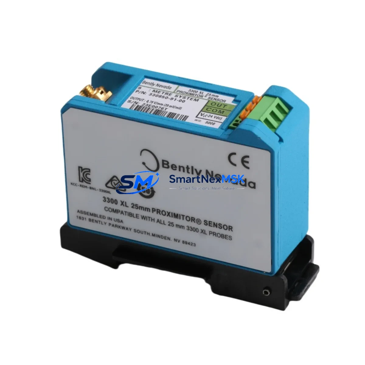
Bently Nevada 330850-91-05 Retrofit-Ready Proximitor Sensor for 3300 XL Control Systems
The Bently Nevada 330850-91-05 is a 25 mm eddy-current Proximitor Sensor engineered for seamless integration into Bently Nevada 3300 XL vibration monitoring systems. As legacy machinery protection platforms approach end-of-life and OEM spare-part availability tightens, plant engineers and reliability teams increasingly rely on verified retrofit-ready replacements to sustain continuous operation without committing to a full system overhaul. This unit is fully compatible with the 3300 XL signal-conditioning architecture, preserving existing wiring harnesses, terminal assignments, and 4–20 mA output loops so that field installation can be completed during a planned maintenance window rather than an unscheduled outage.
Before installing the 330850-91-05 into an existing rack, technicians should confirm the following: the power supply rail delivers a stable –24 VDC (±1 V) to the Proximitor; the barrier terminal strip pinout matches the original 330850 series wiring diagram; the 3300 XL monitor module (such as the 3300/16 or 3300/20 series) is configured for the correct gap voltage range (typically –10 VDC at 1.0 mm gap); and the extension cable (e.g., 330130 series) length is accounted for in the system scale factor calibration. Skipping any of these checks is the most common cause of false-alarm trips during commissioning.
For sites migrating from older Bently Nevada 7200 series or 3300/05 monitors, the 330850-91-05 provides a direct electrical replacement path. The probe tip geometry and thread specification (M8 × 1.0) are identical to the discontinued 330850-91-00 and 330850-91-01 variants, so existing probe holders and armour-jacketed conduit runs can be reused without modification. Pair this sensor with a 330180 extension cable and a 330500 Proximitor housing to reconstruct a complete measurement chain that meets API 670 fifth-edition requirements.
Upgrade Compatibility Table
| Parameter | 330850-91-05 (This Unit) | Legacy / Replaced Models |
|---|---|---|
| Probe Tip Diameter | 25 mm | 25 mm (330850-91-00, -01) |
| Thread Specification | M8 × 1.0 | M8 × 1.0 (compatible) |
| Supply Voltage | –24 VDC | –24 VDC (3300 XL rack) |
| Output Signal | –10 VDC / 200 mV·mil⁻¹ | Same scale factor |
| Monitor Compatibility | 3300/16, 3300/20, 3300/46, 3300/55 | 3300/05, 7200 series (with adapter) |
| Communication Protocol | Analogue 4–20 mA / Modbus RTU (via 3300 gateway) | Analogue only (7200 series) |
| Backplane / Rack Interface | 3300 XL standard backplane | Requires 3300 XL rack upgrade if migrating from 7200 |
| Installation Requirement | Probe holder reuse; re-gap to –10 VDC | Re-calibrate scale factor after swap |
| Commissioning Focus | Gap voltage, cable length, barrier terminal check | Verify HMI tag mapping in System 1 / DCS historian |
| Warranty | 12 Months — covers manufacturing defects and functional failure under normal operating conditions | |
Retrofit Planning for Existing Automation Systems
A successful retrofit begins well before the maintenance window opens. Start by auditing the 3300 XL rack to identify which monitor slots are occupied by 3300/16 dual-channel vibration monitors or 3300/46 temperature monitors, and confirm that the rack’s internal power bus can support the additional sensor load. In multi-rack cabinets, the 3300 XL power supply module (typically a 3300/15 or equivalent) should be load-tested before adding sensors to avoid nuisance trips caused by voltage sag on the –24 VDC rail.
Next, trace the 330130 or 330180 extension cables from the junction box back to the monitor rack. Measure the total cable run length and verify it falls within the system scale factor table published in the 3300 XL installation manual. If the existing cable run exceeds the calibrated length, a new extension cable must be cut to the correct specification — do not splice or extend field cables, as this introduces impedance discontinuities that corrupt the gap voltage reading.
For plants running a DCS historian (such as Emerson DeltaV, Honeywell Experion, or ABB 800xA), confirm that the analogue input card receiving the 4–20 mA signal from the 3300 XL gateway is scaled correctly in the DCS engineering units database. If the site has migrated to a Modbus TCP/IP or PROFIBUS DP communication link between the 3300 XL system and the DCS, verify that the register map for the new sensor channel matches the existing HMI faceplate tag assignments. Mismatched register offsets are a common source of incorrect alarm setpoints after a sensor swap.
Where the control cabinet also houses a Bently Nevada 3500 series rack alongside the 3300 XL system, take care to maintain physical separation between the two backplane buses during the retrofit. The 3500 series uses a different I/O module addressing scheme, and accidental cross-connection of barrier terminals can cause both systems to fault simultaneously. Label all terminal blocks before disconnecting any wiring, and photograph the as-found configuration for reference during re-commissioning.
Finally, if the plant’s safety instrumented system (SIS) receives a hardwired trip signal from the 3300 XL monitor, coordinate with the SIS engineer to place the relevant SIL-rated loop in bypass mode before removing the old sensor. Restore the bypass only after the new 330850-91-05 has been gapped, calibrated, and confirmed healthy in the monitor’s status display. This sequence protects against spurious process shutdowns and satisfies most site management-of-change (MOC) procedures.
Downtime Control During System Migration
Minimising unplanned downtime during a Proximitor sensor swap requires a structured hot-swap protocol. Where the 3300 XL monitor supports channel bypass (available on 3300/16 and 3300/20 firmware revisions 3.x and above), activate the bypass on the affected channel before disconnecting the old sensor. This suppresses the open-circuit alarm that would otherwise propagate to the DCS and trigger an operator response or automatic shutdown.
Prepare the replacement 330850-91-05 on the bench before entering the field: pre-set the probe gap using a calibrated gap tool to achieve –10.0 VDC (±0.1 V) at the nominal 1.0 mm air gap, and record the as-left gap voltage on the work order. Bring a calibrated digital voltmeter and a laptop loaded with Bently Nevada System 1 software (or the equivalent rack configuration utility) to the field so that the channel can be verified live without returning to the control room between steps.
Once the new sensor is installed and gapped, release the channel bypass and observe the vibration reading for a minimum of five minutes at normal operating speed. Compare the reading against the baseline trend stored in the historian. A deviation of more than ±5 % from the pre-swap baseline warrants a re-gap and re-calibration before the work order is closed. Document the as-found and as-left gap voltages, the extension cable serial number, and the monitor firmware version in the plant’s maintenance management system (CMMS) to support future reliability analysis.
For sites where channel bypass is not available, coordinate with operations to reduce machine speed to a safe crawl speed during the swap interval. This limits the vibration amplitude and reduces the risk of a high-vibration trip while the sensor circuit is open. The total swap time for an experienced technician — including gap setting and functional verification — is typically 20 to 40 minutes per channel, making it feasible to complete a two-channel replacement within a single four-hour maintenance window.
Retrofit Support FAQ
Q1: Is the 330850-91-05 a direct drop-in replacement for the discontinued 330850-91-00?
Yes. The 330850-91-05 shares the same probe tip diameter (25 mm), thread specification (M8 × 1.0), supply voltage (–24 VDC), and output scale factor (200 mV·mil⁻¹) as the 330850-91-00 and 330850-91-01. No wiring changes or monitor reconfiguration are required for a like-for-like swap within the 3300 XL system. Re-gap the probe to –10.0 VDC after installation and verify the reading in System 1 before closing the work order.
Q2: What commissioning checks are mandatory before returning the channel to service?
Three checks are non-negotiable: (1) gap voltage must read –10.0 VDC ±0.1 V at the nominal air gap; (2) the extension cable length must match the scale factor entered in the monitor configuration; and (3) the alarm and danger setpoints must be confirmed active and correctly scaled in both the 3300 XL monitor and the DCS historian tag. Additionally, verify that the HMI faceplate displays a healthy status and that no latched alarms remain after the channel bypass is released.
Q3: Can this sensor be used with a Bently Nevada 3500/42M monitor?
The 330850-91-05 is optimised for the 3300 XL signal-conditioning architecture. While the 3500/42M monitor accepts 25 mm Proximitor inputs, it requires a sensor from the 330900 series (3500-compatible) for full specification compliance. Using a 3300 XL sensor on a 3500 monitor may produce acceptable readings in some installations, but it is not factory-supported and may affect SIL certification. Contact our technical team for a cross-reference to the correct 3500-series replacement if your rack is a 3500 platform.
Q4: What does the 12-month warranty cover, and how is a claim initiated?
The 12-month warranty covers manufacturing defects and functional failure under normal operating conditions, including open-circuit probe failures, output signal drift beyond published specification, and connector corrosion attributable to manufacturing. It does not cover damage caused by incorrect gap setting, reverse polarity connection, or mechanical impact. To initiate a warranty claim, contact [email protected] with the purchase order number, installation date, and a description of the failure mode. A replacement unit or credit will be issued within five business days of fault confirmation.
© 2026 SMARTNEXMSK. All rights reserved.
Original Source: https://smartnexmsk.com
Contact: [email protected] | +86 18259474341



