
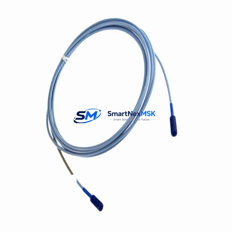
Bently Nevada 330851-000-070-10-00-05: Retrofit-Ready 5mm Proximity Probe for 3300 XL Vibration Monitoring Systems
The Bently Nevada 330851-000-070-10-00-05 is a 5mm eddy-current proximity probe engineered for the 3300 XL series machinery protection and condition monitoring platform. As legacy 3300 XL installations continue to operate across turbines, compressors, pumps, and rotating machinery in oil & gas, power generation, and petrochemical facilities, sourcing verified replacement probes has become a critical maintenance priority. This unit provides a direct, drop-in retrofit solution for sites that need to restore vibration monitoring continuity without replacing the entire transducer system or reconfiguring the monitor rack.
Whether you are replacing a probe damaged by mechanical contact, building a strategic spare-parts inventory for a long-term service contract, or executing a phased upgrade of an aging condition monitoring system, the 330851-000-070-10-00-05 delivers the sensitivity, gap voltage linearity, and cable termination compatibility required for seamless integration into your existing 3300 XL rack architecture.
Upgrade Compatibility Table
| Parameter | Details |
|---|---|
| SKU / Part Number | 330851-000-070-10-00-05 |
| Brand | Bently Nevada |
| Compatible Platform | 3300 XL Machinery Protection System |
| Probe Type | 5mm Eddy-Current Proximity Probe |
| Cable Length | 7.0 m (standard configuration) |
| Connector Type | 3-pin MIL-spec connector (compatible with 3300 XL extension cable) |
| Backplane / Rack Interface | 3300 XL Monitor Rack (compatible with 3300/16 and 3300/20 rack frames) |
| Installation | Threaded probe tip, locknut mounting into proximity probe holder |
| Supply Voltage | −24 VDC (supplied via 3300 XL monitor channel) |
| Communication Compatibility | Analog 4–20 mA / voltage output to 3300 XL monitor; compatible with System 1 condition monitoring software |
| Replacement Recommendation | Direct replacement for 330851-000-070-10-00-05 and compatible with 330780 extension cable and 330180 proximitor sensor |
| Commissioning Notes | Verify gap voltage (−10 VDC nominal at 1.0 mm gap); confirm probe tip-to-target material and surface finish before energizing monitor channel |
| Warranty | 12 Months — covers manufacturing defects and functional failure under normal operating conditions |
Retrofit Planning for Existing Automation Systems
Integrating the 330851-000-070-10-00-05 into a legacy 3300 XL installation requires a structured pre-installation review. Begin by auditing the existing monitor rack — typically a 3300/16 rack or 3300/20 rack — to confirm the channel assignment and monitor module type. The most common paired monitor is the 3300/25 Dual Vibration Monitor or the 3300/55 Keyphasor Module, both of which accept the standard 3300 XL transducer input. Confirm that the monitor channel is configured for a 5mm probe and that the OK setpoint thresholds are appropriate for the replacement unit.
Power budget verification is straightforward for proximity probe systems: the −24 VDC bias supply is provided directly by the monitor channel and does not require a separate external power supply. However, if the rack also houses 3300/46 temperature monitor modules, 3300/32 relay output modules, or a 3300/95 communication gateway module for Modbus or FOUNDATION Fieldbus integration, confirm that the rack power supply — typically a 3300/10 power supply module — is operating within its rated output capacity before adding or replacing transducer channels.
Extension cable routing must be reviewed before installing the replacement probe. The 330780 extension cable connects the probe to the 330180 proximitor sensor (driver), which in turn feeds the monitor channel. Inspect the extension cable for jacket damage, connector corrosion, and continuity. A degraded extension cable is a common source of erratic gap voltage readings that can be misdiagnosed as a failed probe. Replace the extension cable if resistance or capacitance measurements fall outside the 3300 XL transducer system specification.
Gap setting is the most critical commissioning step. Using a calibrated DC voltmeter, adjust the probe tip-to-target gap until the proximitor output reads −10.0 VDC ±0.5 VDC at the nominal 1.0 mm gap for a 5mm probe on a standard AISI 4140 steel target. For non-standard target materials — including stainless steel, titanium, or Inconel — apply the appropriate material correction factor from the 3300 XL transducer system calibration manual. Document the as-found and as-left gap voltage values for the maintenance record.
For sites running System 1 Condition Monitoring Software connected to the 3300 XL rack via a 3300/95 gateway or direct serial link, confirm that the channel tag, engineering unit scaling, and alarm setpoints in the System 1 database reflect the replacement probe’s sensitivity (typically 7.87 V/mm for a 5mm probe). A sensitivity mismatch between the software configuration and the installed transducer will produce incorrect vibration amplitude readings and may trigger false alarms or mask real machinery faults.
If the retrofit is part of a broader migration toward the 3500 Series Machinery Protection System, the 330851-000-070-10-00-05 can serve as a bridge transducer during the transition period — maintaining vibration monitoring on the legacy 3300 XL rack while new 3500/42M Proximitor/Seismic Monitor channels are staged for the incoming 3500 rack. This phased approach avoids a full monitoring blackout and allows alarm setpoints to be validated in parallel before the final cutover.
Downtime Control During System Migration
Minimizing unplanned downtime during a proximity probe replacement requires preparation before the maintenance window opens. The first step is to document the current channel status in the 3300 XL monitor — recording the OK relay state, gap voltage, vibration amplitude (in mils peak-to-peak or µm), and any active alarms — using the front-panel display or the System 1 software historian. This baseline data is essential for post-replacement functional verification and for demonstrating that the replacement probe meets the original performance specification.
Before removing the failed probe, confirm with the operations team whether the machine can be taken offline or whether a hot-swap is required under a bypass permit. For critical machinery — such as steam turbines, centrifugal compressors, or boiler feed pumps — the 3300 XL monitor channel must be bypassed in the safety logic before the probe is disconnected, to prevent a spurious trip on the OK relay. Use the monitor’s front-panel bypass switch or the System 1 software bypass function, and ensure the bypass is logged in the permit-to-work system.
During the physical replacement, use the original probe holder and locknut to maintain the correct probe-to-target geometry. If the probe holder shows wear or thread damage, replace it before installing the new probe — a misaligned probe tip will produce a non-linear gap voltage curve that cannot be corrected by gap adjustment alone. After seating the new probe and setting the gap voltage, restore the monitor channel from bypass and confirm that the OK relay energizes and the vibration reading is within the expected baseline range before releasing the machine to operations.
Post-replacement commissioning should include a 30-minute observation period at normal operating speed, with vibration trend data logged in System 1 to confirm that the replacement probe tracks the machine’s vibration signature consistently. For critical protection channels — such as radial vibration on a high-speed compressor or axial position on a thrust bearing — a witnessed functional test of the alert and danger setpoints is recommended before closing the maintenance work order.
Retrofit Support FAQ
Q1: Is the 330851-000-070-10-00-05 a direct replacement for earlier 330851 series variants?
Yes. The 330851-000-070-10-00-05 is fully compatible with the 3300 XL transducer system and is a direct functional replacement for earlier 330851 series configurations with the same cable length and connector type. Sensitivity, gap voltage linearity, and connector pinout are identical. No recalibration of the monitor channel is required beyond the standard gap voltage verification procedure.
Q2: What commissioning steps are required after installing the replacement probe?
After physical installation, set the probe-to-target gap to achieve −10.0 VDC ±0.5 VDC at the proximitor output using a calibrated DC voltmeter. Restore the monitor channel from bypass and confirm the OK relay energizes. Verify the vibration amplitude reading in the System 1 software or on the monitor front panel. Perform a 30-minute trend observation at operating speed before closing the maintenance work order. Document as-found and as-left gap voltage values.
Q3: Can this probe be used with a 3500 Series monitor rack?
The 330851-000-070-10-00-05 is designed for the 3300 XL transducer system. Compatibility with 3500 Series monitor channels depends on the specific 3500 monitor module and its configured transducer input type. Consult the 3500 Series monitor module datasheet and confirm transducer input specifications before cross-applying a 3300 XL probe to a 3500 rack channel. For guaranteed compatibility, use 3500-series specified transducers such as the 330730 or 330900 series probes.
Q4: What does the 12-month warranty cover?
All units are covered by a 12-month warranty from the date of shipment. The warranty covers manufacturing defects, functional failure under normal operating conditions, and DOA (dead-on-arrival) units. Each probe undergoes pre-shipment functional testing including gap voltage linearity verification and connector integrity check. Warranty claims are processed via our sales team with a standard RMA procedure. Units damaged by mechanical impact, incorrect gap setting beyond the linear range, or chemical exposure are not covered under warranty terms.
© 2026 SMARTNEXMSK. All rights reserved.
Original Source: https://smartnexmsk.com
Contact: [email protected] | +86 18259474341



