
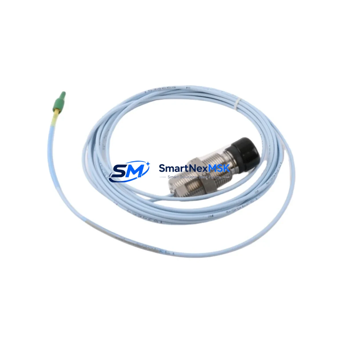
Bently Nevada 330851-02-000-080-10-00-00 Retrofit-Ready Vibration Sensor for Legacy Control Systems
The Bently Nevada 330851-02-000-080-10-00-00 Velomitor XA is a high-temperature, piezoelectric velocity vibration sensor engineered for continuous machinery protection in rotating equipment applications. As legacy Bently Nevada 3300 and 3500 series monitoring systems age out of OEM support cycles, plant engineers and reliability teams increasingly require verified drop-in replacements that preserve existing wiring infrastructure, signal conditioning compatibility, and vibration monitoring logic without triggering full-system overhauls.
This unit delivers a 4–20 mA velocity output signal compatible with the Bently Nevada 3500/42M Proximitor/Seismic Monitor and the 3300/16 Velocity Monitor, allowing direct substitution without reconfiguring rack-level I/O assignments or rewriting monitor setpoint logic. The sensor’s integral cable and connector geometry matches the original field installation footprint, minimizing mechanical retrofit time during planned outages or emergency replacements.
For facilities operating turbines, compressors, pumps, or gearboxes under continuous vibration surveillance, the 330851-02-000-080-10-00-00 is a critical spare that bridges the gap between discontinued OEM supply and uninterrupted machinery protection. SMARTNEXMSK maintains verified stock with pre-shipment functional testing and a 12-month warranty on every unit.
Upgrade Compatibility Table
| Parameter | Detail |
|---|---|
| SKU / Part Number | 330851-02-000-080-10-00-00 |
| Series Compatibility | Bently Nevada 3300, 3500 Monitoring Systems |
| Monitor Compatibility | 3500/42M Proximitor/Seismic Monitor, 3300/16 Velocity Monitor |
| Output Signal | 4–20 mA velocity (piezoelectric) |
| Operating Temperature | High-temperature rated (Velomitor XA specification) |
| Connector / Interface | Integral cable, OEM-matched connector geometry |
| Installation | Direct drop-in; no mechanical modification required |
| Communication Protocol | Analog 4–20 mA; compatible with existing signal conditioners |
| Replacement Recommendation | Direct substitute for discontinued 330851-02-000-080-10-00-00 |
| Commissioning Notes | Verify cable routing, terminal torque, and monitor sensitivity scaling |
| Warranty | 12-Month Warranty — all units pre-tested before shipment |
Retrofit Planning for Existing Automation Systems
Replacing the 330851-02-000-080-10-00-00 in an operating plant requires a structured approach that accounts for the full signal chain — from the sensor mounting pad through the field junction box, into the 3500 rack’s 3500/42M module, and ultimately to the DCS historian or safety system. Before removing the legacy sensor, engineers should document the existing cable tag, terminal block assignments, and the sensitivity value (mV/mm/s or mV/in/s) currently programmed in the monitor channel.
In systems where the 3500 rack also hosts a 3500/22M Transient Data Interface or a 3500/92 Communication Gateway, confirm that the channel mapping in System 1 Evolution software reflects the correct sensor type after substitution. If the plant uses a 3500/20 Rack Interface Module for Modbus or FOUNDATION Fieldbus communication to a DCS such as a Honeywell Experion PKS or Emerson DeltaV, no protocol reconfiguration is typically required for a like-for-like sensor swap — but a channel re-rack or re-enable sequence in the rack configuration software may be necessary to clear latched alerts.
For facilities that have already migrated portions of their machinery protection to the Bently Nevada 3701/40 or 3701/44 standalone monitors, the 330851-02-000-080-10-00-00 remains compatible with the analog input architecture of those platforms, provided the signal conditioner card is configured for velocity input. In mixed-fleet environments where older 3300 racks coexist with newer 3500 racks, maintaining a common sensor model across both platforms simplifies spare parts inventory and reduces technician training overhead.
Wiring adaptation should also account for the field junction box terminal type — whether the installation uses a standard Bently Nevada JB-series junction box or a third-party marshalling panel. Confirm terminal torque specifications and shield grounding practice (single-point ground at the monitor end) before energizing the replacement sensor. If the plant’s cable run exceeds the OEM-specified maximum length for the 4–20 mA loop, verify loop resistance against the monitor’s input impedance specification to avoid signal attenuation errors.
Where the retrofit is part of a broader control cabinet upgrade — for example, replacing an aging Allen-Bradley SLC 500 or Siemens S7-300 PLC that previously handled vibration alarm relay logic — the 330851-02-000-080-10-00-00 can feed directly into a new 3500 rack while the PLC migration proceeds in parallel, decoupling the machinery protection upgrade from the control logic migration timeline.
Downtime Control During System Migration
Minimizing unplanned downtime during a vibration sensor replacement requires pre-staging the replacement unit, verifying its output signal on the bench with a portable signal simulator before installation, and coordinating the swap with the operations team to align with the next scheduled maintenance window or a low-production period.
For critical machinery where continuous monitoring cannot be interrupted, a temporary bypass relay or a portable vibration data collector such as a CSI 2140 or Emerson AMS 2140 can maintain surveillance during the brief period when the permanent monitor channel is offline. Once the 330851-02-000-080-10-00-00 is installed and the terminal connections are verified, restore the monitor channel, confirm the OK relay status on the 3500/42M, and validate the live vibration reading against baseline trend data in System 1 or the plant historian before returning the machine to full load.
If the replacement is triggered by a sensor failure rather than a planned outage, SMARTNEXMSK’s in-stock availability and same-day dispatch capability are designed to compress the procurement-to-installation cycle. All units ship with a pre-test report confirming output signal integrity, connector continuity, and insulation resistance — reducing the risk of receiving a non-functional unit during an emergency repair scenario. The 12-month warranty covers both early-life failures and latent defects identified during commissioning.
Retrofit Support FAQ
Q1: Is the 330851-02-000-080-10-00-00 a direct drop-in replacement for the original Bently Nevada unit?
Yes. This unit matches the original OEM part number and is designed as a direct mechanical and electrical substitute. No modifications to the mounting pad, cable connector, or monitor channel configuration are required for a standard like-for-like replacement in 3300 or 3500 series systems.
Q2: What commissioning steps are required after installation?
After securing the sensor and reconnecting the field cable, re-enable the monitor channel in the 3500 rack configuration software, confirm the OK relay status on the 3500/42M module, and verify the live velocity reading against the machine’s baseline vibration signature. Check that no latched alerts remain from the previous sensor fault before returning the machine to service.
Q3: Can this sensor be used with third-party vibration monitors or DCS analog input cards?
The 4–20 mA output is a standard industrial signal compatible with most DCS analog input modules and third-party vibration monitors that accept velocity sensor inputs. Confirm the input impedance and signal range of the receiving device against the sensor’s output specification before installation in a non-Bently Nevada system.
Q4: What does the 12-month warranty cover, and what pre-shipment testing is performed?
Every unit undergoes pre-shipment functional testing covering output signal integrity, connector continuity, and insulation resistance. The 12-month warranty covers manufacturing defects and early-life failures identified during normal operation or commissioning. Units that fail within the warranty period are replaced or refunded — contact [email protected] to initiate a warranty claim.
© 2026 SMARTNEXMSK. All rights reserved.
Original Source: https://smartnexmsk.com
Contact: [email protected] | +86 18259474341



