
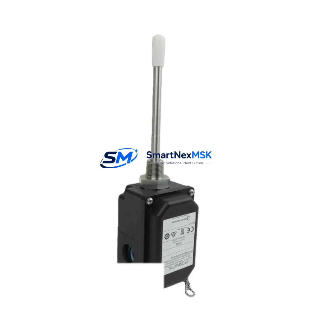
Bently Nevada 330881-16-00-385-06-02 3300 XL Spare: Precision Replacement for Vibration Monitoring Systems
The Bently Nevada 330881-16-00-385-06-02 is an original eddy-current proximity transducer engineered for continuous shaft vibration and position monitoring in rotating machinery. Designed for the 3300 XL Series, this transducer delivers reliable non-contact measurement in demanding industrial environments including turbines, compressors, pumps, and gearboxes. Maintaining a ready stock of this component is a critical element of any predictive maintenance program — unplanned downtime caused by a failed proximity transducer can cascade into hours of lost production and costly emergency repairs.
At SMARTNEXMSK, every 330881-16-00-385-06-02 unit is sourced from verified supply channels, electrically tested prior to shipment, and backed by a 12-month warranty. Fast dispatch and long-term supply continuity make this listing the preferred source for maintenance engineers and procurement teams managing aging 3300 XL and 3500 Series installations.
Spare Maintenance Table
| Parameter | Specification |
|---|---|
| Part Number | 330881-16-00-385-06-02 |
| Brand | Bently Nevada |
| Series | 3300 XL / 3500 Series Compatible |
| Type | Eddy-Current Proximity Transducer |
| Measurement | Shaft Radial Vibration & Axial Position |
| Cable Length | 385 cm (integrated) |
| Thread Size | M8 (metric) |
| Sensitivity | 7.87 V/mm (200 mV/mil) |
| Operating Temperature | -35°C to +120°C |
| Supply Voltage | -24 VDC (nominal) |
| Output Range | -2 VDC to -18 VDC |
| Gap Range | 0.25 mm to 2.25 mm |
| Ingress Protection | IP67 |
| Compatibility | 3300 XL 8mm Proximitor Sensor, 3500/42M, 3500/40M |
| Origin | USA (OEM) |
| Warranty | 12 Months |
| Pre-shipment Test | Electrical continuity, sensitivity, and output linearity verified |
| Condition | New / Surplus New |
Maintenance Planning for Continuous Operation
When a 330881-16-00-385-06-02 proximity transducer is flagged for replacement during a scheduled outage or emergency shutdown, experienced maintenance engineers know that the transducer itself is rarely the only component requiring attention. A thorough inspection of the complete measurement loop is essential to restore full system integrity and prevent repeat failures.
Begin with the 3300 XL Proximitor Sensor (typically the 330180 or 330130 series), which conditions the transducer signal and must be verified for correct gap voltage and sensitivity calibration after any transducer swap. If the Proximitor output is drifting or saturated, replacement of both the transducer and the Proximitor as a matched pair is strongly recommended.
Inspect the extension cable — commonly the Bently Nevada 330130 or 330180 series armored extension — for insulation damage, connector corrosion, and continuity. A degraded cable introduces noise that mimics shaft vibration anomalies and can trigger false alarms on the 3500/42M Proximitor I/O Module or the 3500/40M Proximitor Monitor. These rack-mounted modules should be checked for firmware revision compatibility and channel calibration status whenever a field transducer is replaced.
At the rack level, verify the 3500/15 Power Supply Module output voltage stability. Voltage sag on the -24 VDC rail directly affects transducer bias voltage and can produce erroneous gap readings. If the power supply is approaching its rated service life, proactive replacement during the same maintenance window eliminates a second unplanned outage.
For installations where the 330881-16-00-385-06-02 monitors axial thrust position, cross-check the 3500/22M Transient Data Interface configuration and ensure the thrust alarm setpoints are re-validated after reinstallation. Simultaneously, inspect the terminal strip and field wiring within the junction box for loose terminations, moisture ingress, and shield grounding continuity — common root causes of intermittent vibration signal faults that are often misattributed to the transducer itself.
Where the 3300 XL system interfaces with a DCS or safety system, confirm that the 4–20 mA output isolator or signal conditioner downstream of the monitor rack is functioning correctly. A failed isolator can corrupt vibration data reaching the control room historian, leading to missed alarm conditions. Finally, review the 3500 System Rack backplane for any signs of connector wear or card-edge oxidation, particularly in high-humidity or coastal environments.
Stocking a minimum of two 330881-16-00-385-06-02 transducers per critical machine train, alongside matched extension cables and at least one spare Proximitor Sensor, is the industry-standard approach for facilities operating continuous processes where unplanned downtime carries significant financial and safety consequences.
Site Replacement Workflow
Step 1 — Isolation & Permit: Obtain a work permit and isolate the measurement loop at the 3500 rack. Do not de-energize the entire rack unless required — most 3500 Series racks support hot-swap of I/O modules, but field transducer replacement requires local isolation at the junction box.
Step 2 — Gap Measurement: Before removing the old transducer, record the installed gap voltage using a calibrated voltmeter at the Proximitor output. This baseline confirms whether the transducer failure was gap-related or electrical.
Step 3 — Transducer Removal: Loosen the locknut and carefully unthread the 330881-16-00-385-06-02 from the bracket. Inspect the probe tip for mechanical damage and the cable jacket for abrasion. Retain the old unit for failure analysis if required by your maintenance management system.
Step 4 — Installation: Thread the new transducer into the bracket and set the gap to the manufacturer-specified nominal value (typically 1.0 mm to 1.5 mm for 8mm probes). Tighten the locknut to the specified torque. Route the cable to avoid contact with hot surfaces or rotating components.
Step 5 — Calibration Verification: Power the loop and verify the Proximitor output voltage falls within the linear range. Confirm the 3500 monitor channel reads correctly and that no alarms are active at the nominal gap.
Step 6 — Documentation: Update the CMMS record with the new serial number, installation date, and gap voltage. Schedule the next inspection interval per your predictive maintenance plan.
This workflow is compatible with direct replacement of legacy 330880 and 330181 series transducers in existing 3300 XL brackets, minimizing mechanical modifications and reducing total replacement time to under 60 minutes for a prepared maintenance team.
Spare Parts Support FAQ
Q1: Is the 330881-16-00-385-06-02 a direct replacement for older 330880 series transducers?
Yes. The 330881 series is the current-generation replacement for the 330880 family. Mechanical dimensions, thread size, and cable connector are compatible with existing 3300 XL brackets. Sensitivity and output characteristics are identical, requiring no recalibration of the Proximitor Sensor in most installations. Always verify the gap voltage after installation.
Q2: How do you verify compatibility with a 3500/42M or 3500/40M monitor module?
Compatibility is confirmed by matching the transducer system type (8mm eddy-current, 200 mV/mil sensitivity) to the monitor channel configuration. Check the 3500 rack configuration software (System 1 or Rack Configuration Software) to confirm the channel is set for the 3300 XL 8mm transducer system. No hardware modification is required.
Q3: What pre-shipment testing is performed on each unit?
Every 330881-16-00-385-06-02 shipped by SMARTNEXMSK undergoes electrical continuity testing, static sensitivity verification, and output linearity check across the full gap range. Units that do not meet OEM specifications are quarantined and not shipped. A test report is available upon request for critical applications.
Q4: What is the warranty coverage and what does it include?
All units carry a 12-month warranty from the date of shipment. The warranty covers electrical failure under normal operating conditions and includes free replacement or full refund. It does not cover mechanical damage caused by improper installation, over-torquing, or exposure to conditions outside the rated operating envelope. SMARTNEXMSK maintains long-term stock of this part number to support warranty replacements and ongoing procurement needs.
© 2026 SMARTNEXMSK. All rights reserved.
Original Source: https://smartnexmsk.com
Contact: [email protected] | +86 18259474341



