
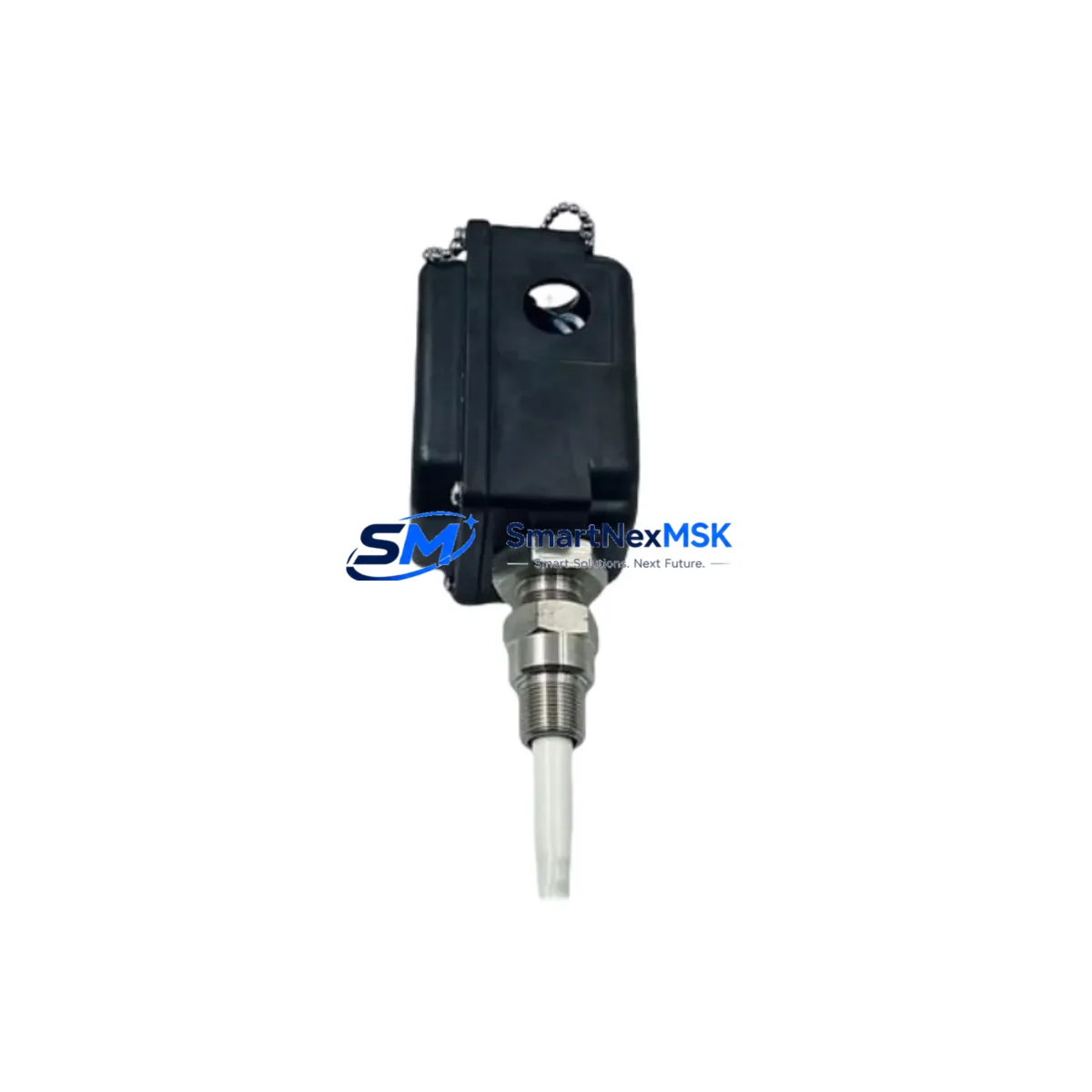
Bently Nevada 330881-16-10-105-06-02 Retrofit-Ready Proximity Transducer for Legacy Control Systems
The Bently Nevada 330881-16-10-105-06-02 is a PROXPAC XL eddy current proximity transducer engineered for continuous shaft vibration and position monitoring in rotating machinery protection systems. As legacy Bently Nevada 3300 Series and 7200 Series installations reach end-of-service life, this unit serves as a verified retrofit-ready replacement that preserves existing wiring infrastructure, signal conditioning architecture, and machinery protection logic without requiring a full system overhaul.
Industrial facilities operating steam turbines, gas compressors, centrifugal pumps, and large induction motors rely on proximity transducers to deliver real-time radial vibration, axial position, and differential expansion data to the Bently Nevada 3500 Series Machinery Protection System. The 330881-16-10-105-06-02 is dimensionally and electrically compatible with the 3300 XL 8mm transducer family, making it a direct candidate for drop-in replacement in existing probe installations where the extension cable, proximitor, and rack-mounted monitor cards remain serviceable.
When planning a retrofit around this transducer, engineers must verify the complete measurement chain. The proximitor module — typically a 330180 Series or 330130 Series proximitor — must be confirmed compatible with the 330881 probe body and the associated extension cable assembly. Extension cables such as the 330130-080-00-00 or 330130-045-00-00 must be inspected for continuity and shielding integrity before reuse. The Bently Nevada 3500/42M Proximitor/Seismic Monitor or 3500/40M Proximitor Monitor card in the 3500 rack must be configured to match the transducer’s sensitivity output, typically –7.87 V/mm (–200 mV/mil), to ensure accurate vibration amplitude readings.
Upgrade Compatibility Table
| Parameter | 330881-16-10-105-06-02 (This Unit) | Retrofit Notes |
|---|---|---|
| Transducer Type | Eddy Current / PROXPAC XL | Compatible with 3300 XL and 3500 Series monitor cards |
| Probe Diameter | 8 mm | Fits standard 8 mm probe holder; verify thread engagement depth |
| Cable Length | 1.0 m (probe body) | Pair with 330130 Series extension cable to reach proximitor |
| Sensitivity | –200 mV/mil (–7.87 V/mm) | Must match monitor card configuration in 3500 rack |
| Gap Voltage Range | –2 VDC to –18 VDC | Set gap to –10 VDC nominal during installation |
| Supply Voltage | –24 VDC (via proximitor) | Confirm 3500 rack power supply capacity before adding modules |
| Communication Compatibility | Analog 4–20 mA / direct to 3500 monitor | No protocol migration required; analog signal chain preserved |
| Replacement Recommendation | Direct drop-in for 330881 family probes | Inspect probe tip, cable jacket, and connector pins before reuse |
| Commissioning Focus | Gap setting, sensitivity verification, OK relay check | Use Bently Nevada field calibration procedure TN-13 |
| Warranty | 12 Months | Covers manufacturing defects; includes pre-shipment functional test |
Retrofit Planning for Existing Automation Systems
A successful retrofit using the 330881-16-10-105-06-02 begins well before the maintenance window opens. The first step is a full audit of the existing measurement chain. Technicians should document the current probe gap voltage at operating temperature, the extension cable routing and connector condition, and the proximitor mounting location. If the existing proximitor — such as a 330180-51-05 or 330180-91-05 — shows signs of drift or output instability, it should be replaced simultaneously to avoid a repeat outage.
The 3500 rack housing the monitor cards must be assessed for available slot capacity if additional I/O channels are being added as part of a broader upgrade. The 3500/20 Rack Interface Module and 3500/22M Transient Data Interface should be confirmed operational, as these modules govern communication between the protection system and the plant DCS or historian. In facilities using a Rockwell Automation ControlLogix or Allen-Bradley PLC-5 platform for supervisory control, the analog input cards receiving 4–20 mA vibration signals from the 3500 system must be verified for input range and scaling configuration.
For plants migrating from older Bently Nevada 7200 Series transducers to the 3300 XL / 330881 platform, the probe holder thread specification and radial clearance in the bearing housing must be re-checked. The 7200 Series used a different probe body diameter and thread pitch, so a new probe holder insert may be required. The extension cable connector type also differs between generations, making a full cable replacement advisable rather than using adapters in a high-vibration environment.
Where the plant control architecture includes a Yokogawa CENTUM VP DCS or Honeywell Experion PKS system receiving machinery protection data via Modbus RTU or OPC-DA from the 3500 gateway, the data mapping tables should be reviewed to confirm that the channel address assignments remain consistent after the transducer swap. Any change in channel numbering within the 3500 rack will require a corresponding update in the DCS tag database and historian configuration.
HMI screens displaying shaft vibration trends — whether running on a Wonderware InTouch, iFIX, or Ignition SCADA platform — should be reviewed to confirm that the engineering unit scaling and alarm setpoints remain valid after the replacement. If the new transducer’s sensitivity output differs by more than 1% from the unit being replaced, the monitor card’s OK setpoint and danger/alert thresholds should be recalibrated before returning the machine to service.
Downtime Control During System Migration
Minimizing unplanned downtime during a proximity transducer replacement requires a structured pre-outage preparation protocol. Before the maintenance window, the replacement 330881-16-10-105-06-02 unit should be bench-tested using a Bently Nevada field calibration kit to confirm sensitivity output and gap voltage linearity. All replacement components — including the extension cable, proximitor, and any required probe holder hardware — should be staged and kitted at the work site.
During the outage, the existing probe should be removed carefully to avoid damaging the probe holder threads. The new probe body should be installed and gapped to –10 VDC nominal using a calibrated digital voltmeter before the machine is returned to turning gear. The OK relay output on the 3500 monitor card should be verified before the protection system is re-armed.
To protect the original control program logic, no changes should be made to the 3500 rack configuration file or the DCS control strategy during the transducer swap unless a deliberate upgrade is planned and tested in advance. The existing program backup should be archived before any rack configuration changes are attempted. If the plant uses a Bently Nevada System 1 condition monitoring software platform, the asset configuration should be exported and saved before the maintenance window begins.
For facilities where continuous operation is critical, a hot-standby or redundant measurement channel strategy using a second 330881-series probe on the same bearing journal can allow the primary channel to be serviced without triggering a machine trip. This approach requires the 3500 monitor card to support dual-channel voting logic, which should be confirmed in the rack configuration before the outage plan is finalized.
Retrofit Support FAQ
Q1: Is the 330881-16-10-105-06-02 a direct replacement for other 330881 suffix variants?
A: The 330881 base part number designates the PROXPAC XL 8 mm probe family. Suffix digits encode cable length, connector type, and temperature rating. The -16-10-105-06-02 configuration specifies a 1.0 m armored cable with standard connectors rated for typical industrial ambient conditions. Before substituting across suffix variants, confirm that the cable length, connector pinout, and temperature rating are compatible with the existing installation. When in doubt, contact our technical team with the original part number for a confirmed cross-reference.
Q2: What commissioning steps are required after installation?
A: After mechanical installation, set the probe gap to achieve –10 VDC output at the proximitor with the shaft stationary. Verify the OK relay is energized and the vibration channel reads within the expected baseline range. Confirm alert and danger setpoints in the 3500 monitor card match the machinery OEM’s vibration limits. Document the as-found and as-left gap voltage readings in the maintenance record. A full slow-roll vibration check at turning gear speed is recommended before returning the machine to full load.
Q3: Can this transducer be used with non-Bently Nevada monitor systems?
A: The 330881-16-10-105-06-02 outputs a standard eddy current analog signal compatible with any monitor system designed for –200 mV/mil sensitivity probes operating on a –24 VDC supply. It can interface with third-party vibration monitors from vendors such as Metrix, Emerson, or PCB Piezotronics provided the monitor’s input specification matches. Signal conditioning and OK threshold logic will need to be configured in the third-party monitor to match the transducer’s output characteristics.
Q4: What does the 12-month warranty cover, and is pre-shipment testing performed?
A: Every unit undergoes a functional pre-shipment test verifying sensitivity output, gap voltage linearity, and cable continuity before dispatch. The 12-month warranty covers manufacturing defects in materials and workmanship from the date of shipment. It does not cover damage resulting from improper installation, mechanical impact, or operation outside the specified environmental limits. Warranty claims are processed with a return authorization; replacement units are dispatched within 3 business days of confirmed fault verification.
© 2026 SMARTNEXMSK. All rights reserved.
Original Source: https://smartnexmsk.com
Contact: [email protected] | +86 18259474341



