
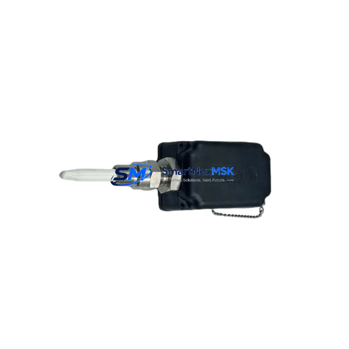
Bently Nevada 330881-28-10-100-03-02 Maintenance-Ready Spare for 3300 XL Automation
The Bently Nevada 330881-28-10-100-03-02 is a PROXPAC Proximity Transducer Assembly engineered for continuous-duty vibration and position monitoring in rotating machinery protection systems. Designed for direct integration with the Bently Nevada 3300 XL monitoring platform, this assembly delivers reliable eddy-current sensing performance in demanding industrial environments including turbines, compressors, pumps, and gearboxes. For maintenance engineers managing aging machinery protection infrastructure, having a verified spare of the 330881-28-10-100-03-02 on hand is a critical element of any proactive maintenance strategy.
This unit ships fully tested and verified against Bently Nevada factory specifications. Each assembly undergoes output voltage linearity checks, gap calibration verification, and cable continuity testing prior to dispatch. A 12-month warranty is included with every unit, covering manufacturing defects and performance deviations under normal operating conditions. Worldwide shipping is available with lead times confirmed at order placement.
For procurement engineers sourcing long-lead or discontinued Bently Nevada components, the 330881-28-10-100-03-02 is available from verified industrial surplus and authorized distribution channels. Maintaining a minimum buffer stock of one to two units per critical machine train is strongly recommended, particularly for facilities operating 3300 XL systems that are no longer in active production support cycles.
Spare Maintenance Table
| Parameter | Specification / Detail |
|---|---|
| SKU / Part Number | 330881-28-10-100-03-02 |
| Brand | Bently Nevada |
| Series | 3300 XL PROXPAC |
| Product Type | Proximity Transducer Assembly |
| Sensing Technology | Eddy-Current (Non-contact) |
| Probe Tip Diameter | 28 mm |
| Cable Length | 10 ft (approx. 3 m) integral cable |
| Extension Cable Length | 100 ft (approx. 30 m) — per SKU suffix |
| Driver / Oscillator | 3300 XL Proximitor® (external, rack-mounted) |
| Output Signal | -18 VDC nominal (linear range) |
| Supply Voltage | -24 VDC (from Proximitor® driver) |
| Operating Temperature | -35°C to +121°C (probe tip) |
| Target Material Compatibility | AISI 4140 steel (standard); other alloys require calibration |
| Monitor Compatibility | Bently Nevada 3300 XL, 3500 Series (with appropriate driver) |
| Installation | Threaded probe holder, standard 3300 XL bracket mounting |
| Replacement Compatibility | Direct drop-in for same-suffix 330881 series assemblies |
| Condition | New / Surplus New / Tested Refurbished (specify at order) |
| Warranty | 12 Months from shipment date |
| Origin | USA |
| Shipping | Worldwide — DHL, FedEx, UPS available |
Maintenance Planning for Continuous Operation
When scheduling a replacement of the 330881-28-10-100-03-02 during a planned outage or emergency shutdown, maintenance engineers should treat the transducer assembly as part of a broader inspection scope rather than an isolated component swap. The PROXPAC assembly works in conjunction with the 3300 XL Proximitor® driver module — typically a 330180 or 330130 series unit — which should be inspected for output drift, connector corrosion, and power supply stability before the new transducer is commissioned.
The extension cable connecting the probe to the Proximitor® driver is a frequent source of signal degradation in long-service installations. The 330130-045-00-CN or equivalent 3300 XL extension cable should be checked for jacket integrity, shield continuity, and connector pin condition. Damaged extension cables can introduce noise into the vibration signal chain and cause false alerts or missed trips even after a probe replacement.
At the rack level, the 3500/42M Proximitor®/Seismic Monitor or the 3300 XL rack-mounted monitor card should be verified for firmware revision compatibility and channel configuration before the replacement probe is energized. If the facility is running a mixed rack with both 3300 XL and 3500 Series cards, confirm that the driver voltage and scale factor settings match the 330881-28-10-100-03-02 calibration curve.
Terminal blocks and field wiring within the junction box or marshalling cabinet should be inspected during the same maintenance window. Loose or corroded terminals on the signal pair (SIG and COM) or the power supply lines (-24 VDC and COM) are a common root cause of intermittent vibration readings. Replacing worn terminal blocks — such as Phoenix Contact or Weidmüller DIN-rail types rated for the signal voltage — during the same outage avoids repeat access to confined spaces.
For facilities with Bently Nevada System 1 or System 1 Evolution software, the replacement probe should be re-gapped and the gap voltage recorded in the asset history. The recommended gap voltage for the 330881-28-10-100-03-02 on AISI 4140 steel is typically -10.0 VDC ±0.5 VDC at the nominal 50 mil (1.27 mm) gap. Any deviation beyond this range after installation should prompt a re-check of the extension cable and Proximitor® driver output.
If the maintenance scope includes an HMI update or DCS integration check, verify that the analog input card receiving the -18 VDC proximity signal — such as a Honeywell HC900 AI module or an Emerson DeltaV 4–20 mA converter card — is correctly scaled and that alarm setpoints have not drifted from the baseline established during the original commissioning. Signal isolators in the loop, such as a Pepperl+Fuchs KFD2-series barrier or a MTL5000-series Zener barrier, should also be tested for output accuracy if the installation is in a hazardous area.
Site Replacement Workflow
A structured on-site replacement of the 330881-28-10-100-03-02 minimizes downtime and reduces the risk of introducing new faults during the swap. The following workflow is recommended for maintenance teams performing a first-time replacement or returning to a machine after an extended service interval:
Step 1 — Pre-shutdown verification: Confirm the existing probe output voltage at the Proximitor® driver terminal. Record the gap voltage, vibration baseline (in mils peak-to-peak), and any active alarms. This data serves as the acceptance benchmark for the replacement unit.
Step 2 — Isolation and de-energization: Isolate the -24 VDC supply to the affected Proximitor® driver channel. Do not de-energize the entire rack unless required by site safety procedures, as adjacent channels may be monitoring other critical machine trains.
Step 3 — Probe removal: Disconnect the extension cable at the field junction box. Remove the probe from the holder using the appropriate spanner, taking care not to damage the probe tip or the threaded holder bore. Inspect the holder for thread wear or contamination.
Step 4 — New probe installation: Install the 330881-28-10-100-03-02 into the cleaned holder. Set the gap to the nominal value using a feeler gauge or the gap voltage method. Reconnect the extension cable, ensuring the connector is fully seated and the locking ring is tightened.
Step 5 — Re-energization and gap verification: Restore the -24 VDC supply. Measure the gap voltage at the Proximitor® driver output terminal. Confirm the reading is within the acceptable range before releasing the channel from bypass.
Step 6 — Functional test and documentation: Verify that the vibration reading on the monitor or DCS display is stable and consistent with the pre-shutdown baseline. Update the maintenance management system (CMMS) with the replacement date, new probe serial number, gap voltage, and technician sign-off. Retain the removed probe for failure analysis if the replacement was unplanned.
Spare Parts Support FAQ
Q1: Is the 330881-28-10-100-03-02 a direct replacement for other 330881 suffix variants?
The 330881 series uses a structured suffix system where the digits encode probe diameter, integral cable length, extension cable length, and connector type. The -28-10-100-03-02 suffix specifies a 28 mm probe, 10 ft integral cable, 100 ft extension, and a specific connector configuration. Cross-suffix substitution is possible in some cases but requires verification of the gap calibration curve and connector compatibility with the installed Proximitor® driver. Contact our technical team with your existing installation details for a confirmed cross-reference before ordering.
Q2: What pre-shipment testing is performed on each unit?
Every 330881-28-10-100-03-02 unit is tested for output voltage linearity across the full gap range, cable continuity and shield integrity, and connector pin engagement. New and surplus-new units are tested against Bently Nevada factory calibration data. Refurbished units undergo the same electrical tests plus a visual inspection of the probe tip, cable jacket, and connector body. A test report is available upon request for critical applications.
Q3: How should I store spare units to maintain long-term reliability?
Store the 330881-28-10-100-03-02 in its original packaging or an equivalent anti-static, moisture-resistant enclosure. Recommended storage conditions are 15°C to 35°C with relative humidity below 70%, non-condensing. Avoid storing near strong magnetic fields or sources of mechanical vibration. Inspect stored units annually for connector corrosion and cable jacket condition. Units stored correctly for up to five years typically perform within specification when deployed.
Q4: What does the 12-month warranty cover, and how is a claim processed?
The 12-month warranty covers manufacturing defects, calibration deviations, and premature failure under normal operating conditions as defined by Bently Nevada application guidelines. It does not cover damage resulting from incorrect installation, overvoltage, mechanical impact, or use outside the rated environmental envelope. To initiate a warranty claim, contact [email protected] with the order number, unit serial number, a description of the failure mode, and any available site data (gap voltage, vibration readings, alarm history). Replacement units are dispatched after failure verification, with return shipping of the defective unit required for refurbished stock claims.
© 2026 SMARTNEXMSK. All rights reserved.
Original Source: https://smartnexmsk.com
Contact: [email protected] | +86 18259474341



